Part 7: Joint design and installation during downtime
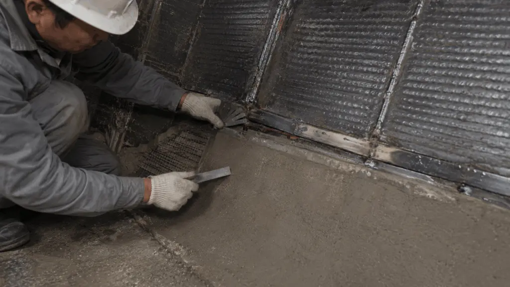
Joints are often among the first areas of a lining system to develop damage.
This is because joints create gaps, edges and transition areas. These three features allow bulk material to enter the gap, act directly on exposed edges or change the gap condition as temperature varies.
For this reason, joint design is not simply a matter of dividing plates according to available dimensions. Joint position, overlap direction, gap and installation sequence need to be determined according to the actual material-flow direction and the thermal conditions of the equipment.
These requirements also need to be incorporated into the installation schedule. When available downtime is limited, mandatory material waiting periods still need to be maintained.
If actual downtime is shortened, the work scope should be adjusted rather than reducing the time required for materials to reach the necessary condition.
1. Technical terms used in this article
The following terms are used throughout joint arrangement and installation scheduling.
In this article, the installation schedule should be managed by the hour where the work contains stages and waiting periods that require detailed control.
2. Joints need to be controlled as separate areas
A joint differs from the center of a plate because three conditions exist at the same location:
- there is a gap into which material can enter
- there is an edge that may be exposed to impact first
- the gap can change as the lining and supporting structure thermally expand
The final point is particularly important.
A gap that is suitable while the equipment is cold may no longer be suitable when operating temperature increases. The joint condition therefore needs to be considered across the actual temperature range at the location, not only at the time of installation.
3. Joint location should follow the material-flow condition
Not every area of the same component experiences the same material-flow condition.
The principle is to prioritize joint placement in areas where the material has already reached a stable sliding condition.
Joint location should therefore not be determined only by plate dimensions or installation convenience. The direction and condition of material flow at the operating location need to be considered first.
4. Four principles for joint arrangement
Staggered joints break up a continuous gap line across the surface.
If several joints align, they can form a continuous groove. Material flow may then continue to act along this groove.
When joints are staggered, the continuous path is interrupted and the material no longer has one long gap running through several rows.
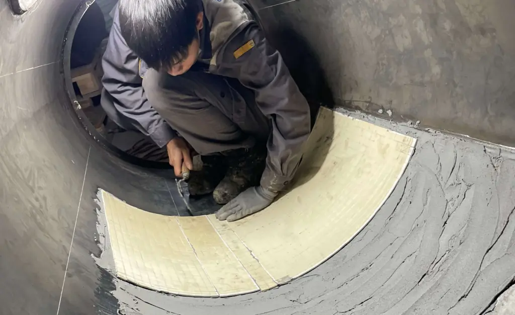
5. Overlap direction needs to follow the material-flow direction
For lap joints:
- the upper edge should be on the incoming-flow side
- the lower edge should be on the outgoing-flow side
This arrangement allows bulk material to slide across the joint instead of striking directly against an exposed edge.
A suitable installation sequence is from downstream toward upstream so that the overlap is formed in the direction of material flow. This principle is discussed in Part 4: Installing anti-adhesion linings.
For other lining systems, a similar arrangement can be considered where joint geometry and fixing methods permit.
6. Joint gaps need to be calculated according to differential thermal expansion
The gap at a joint needs to satisfy two requirements:
- provide enough space to accommodate thermal expansion
- remain narrow enough to prevent bulk material from becoming trapped
The gap should therefore not be estimated directly at the site.
When determining the gap dimension, consider:
- coefficient of thermal expansion of the lining
- coefficient of thermal expansion of the steel supporting structure
- component dimensions
- actual temperature range at the location
The key issue is the difference in thermal expansion between the lining and the supporting structure.
According to the documentation being used, fused cast basalt has a coefficient of thermal expansion of 7.0 × 10⁻⁶/K over the range of 20 to 350 °C.
When values of this type are used in calculations, units and exponent notation need to be checked against the original documentation.
The final gap dimension still needs to be determined according to the actual material combination and thermal conditions at the location.
7. Connection condition needs to be considered before heating a component
The documentation advises against heating the full length of a long component after it has already been welded to the structure.
When the component expands, thermal displacement can transfer load to other welds, including areas outside the location being directly observed.
This consideration applies to components already attached to the structure, such as cutting edges or lining plates.
The same heating operation can therefore produce different results when applied to:
- a free plate
- a component already fixed to the structure
The connection condition of the component needs to be identified before deciding how it should be heated.
8. Installation schedules should be planned by the hour
When downtime is limited, recording only the total number of days is not sufficient for controlling the work.
The schedule needs to show each activity and all periods that cannot be shortened.
The longest sequence determines when the entire work scope can be completed.
Waiting periods within this sequence are particularly important because they cannot be shortened by adding manpower or equipment.
This is also why, in Part 5: Installation at the interface between two material groups, the material group with the longer waiting period is given priority so that part of the waiting time can run in parallel with other work.
9. Prepare contingencies before the equipment is shut down
Once the equipment has stopped, waiting for additional material, tools or manpower directly consumes available installation time.
According to the documentation being used, three groups should be prepared in advance:
Spare lining material helps address cases where a component is rejected or damaged during installation.
Backup tools prevent the entire team from stopping because one piece of equipment fails.
Backup personnel help prevent the work from depending entirely on one individual during a short installation window.
10. If downtime is shortened, adjust the work scope
Mandatory waiting periods are required for material curing, stabilization or reaction.
If actual downtime becomes shorter than planned, the principle should be:
reduce the work scope, not the mandatory waiting time at each location.
The documentation provides the following reference order when scope needs to be reduced:
Each deferred location should be recorded with:
- location not completed
- reason
- planned maintenance period to which the work is moved
This order is intended only to support installation planning.
The final decision should be made by the plant because retaining or deferring a location directly affects the production plan.
11. Items that can be checked immediately after installation
Three simple checks can help identify joint-related deviations before the equipment returns to operation.
The final inspection helps confirm whether the joints have actually been staggered.
If a continuous gap line is still visible across several rows when viewed along the surface, the arrangement has not achieved the intended purpose of breaking up the groove.
12. Schedule records should retain both planned and actual time
The schedule-tracking record should contain four groups of data:
Comparing planned and actual time helps future downtime planning identify:
- activities that are consistently underestimated
- activities that can be organized in parallel
- waiting periods that actually control the schedule
Activity-level data are therefore more useful than retaining only one total duration for the entire installation period.
13. Downtime costs need to use plant-provided data
The value of one hour of production-line downtime depends on the operating conditions of each plant.
The installation contractor can use this value when comparing options if the plant provides the data.
However, the contractor should not independently assign a value on behalf of operations or production.
Data directly related to output, operating losses and downtime costs should come from the plant itself.
14. Responsibilities for joint design and scheduling
Joint and schedule decisions involve design, installation, maintenance and operations.
The installation contractor can recommend which locations should be prioritized and which could be moved to the next maintenance period based on operational impact.
However, the decision to defer a location from a planned downtime period belongs to the plant. It is not a unilateral decision by the installation contractor.
15. Scope of application and references
This article focuses on joint design and organizing installation under limited downtime conditions.
Three points should be noted.
First, gap dimensions depend on the material, component dimensions and actual temperature range. This article explains the principle for determining the gap rather than providing one value or formula applicable to every case.
Second, the actual schedule also depends on the work area, ventilation, access routes and the number of people permitted to work simultaneously. A reliable schedule can therefore only be prepared after installation conditions have been surveyed.
Third, the scope-reduction order presented in this article is a proposal for installation planning. The plant determines which locations remain within the current work scope and which are moved to a later maintenance period.
Values relating to thermal expansion, gaps and material requirements need to be checked against the current applicable technical documentation.
The principle of placing joints in stable sliding-flow zones, identifying the longest sequence of dependent activities and preparing contingencies for downtime are based on field installation experience used in Gia Anh’s methodology.