Part 3: Fixing non-metallic linings: field installation techniques
A non-metallic lining may be made from the correct material but can still detach, fall off or separate from the supporting structure if the fixing method is unsuitable.
For this material group, the failure point is often not the lining itself, but the attachment between the lining and the supporting structure.
With adhesive bonding in particular, even a small area with insufficient adhesive at a tile corner can become the starting point for detachment.
For this reason, installation needs to control substrate preparation, fixing method, installation procedure, mandatory waiting times and signs that can be checked directly in the field.
1. Explanation of key technical terms used in this article
The following terms appear throughout the selection, installation and inspection of non-metallic linings.
Five terms directly related to lining fixation
In addition to the fixing mechanism, non-metallic linings also involve several terms related to how the material performs on the equipment.
In this article, the term lining is used instead of coating.
The word coating may suggest a thin paint-like layer, while this article refers to wear protection systems that are fixed to or formed on a supporting structure using several different mechanisms.
2. Four fixing methods and how to select them
Non-metallic linings are not fixed to the supporting structure using a single method.
Site conditions, equipment geometry, temperature, impact, removal requirements and accessibility can all affect the fixing solution.
2.1. Four main fixing methods
The order above reflects the frequency of occurrence in the project records used as the source. It is not a general industry usage ranking.
One advantage of monolithic systems in suitable locations is the reduction in the number of joints.
Joints are locations where material flow can act directly on gaps or edges. Therefore, where geometry and operating conditions allow, reducing the number of joints also reduces one group of potential failure points.
2.2. Selecting the method according to actual conditions
The table below provides initial guidance before detailed design and installation.
This table is intended for initial guidance and does not replace assessment of the actual site conditions.
A single field condition can eliminate an entire fixing method. For example, if there is no rear-side access, a weld-stud solution may no longer be practical even if the other conditions are suitable.
At the center of a lining tile, the load is distributed over a larger area and the adhesive is mainly subjected to shear.
At the corner, the condition changes. The adhesive is subjected to peel from multiple directions, which is a less favorable loading mode for the bonded joint.
Insufficient adhesive at a corner therefore does more than reduce a small portion of the bonded area. The void occurs precisely in a sensitive area of the joint.
Even a corner area without adhesive that is only about the size of a fingertip can become the starting point for the entire tile to detach after a period of operation.
When a lining falls off, the attachment between the lining and the supporting structure should be checked before concluding that the lining material itself is defective.
4. Monolithic casting, trowelling or spraying
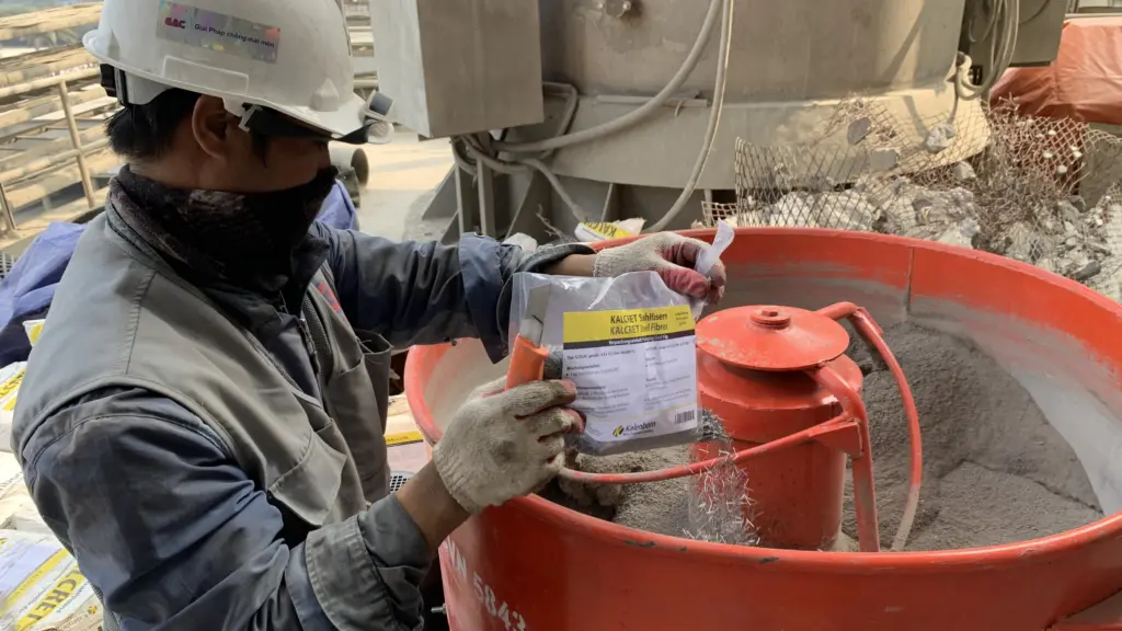
With monolithic methods, bond quality depends directly on substrate preparation, mesh arrangement, material mixing and curing control.
4.1. Substrate preparation, mixing and installation
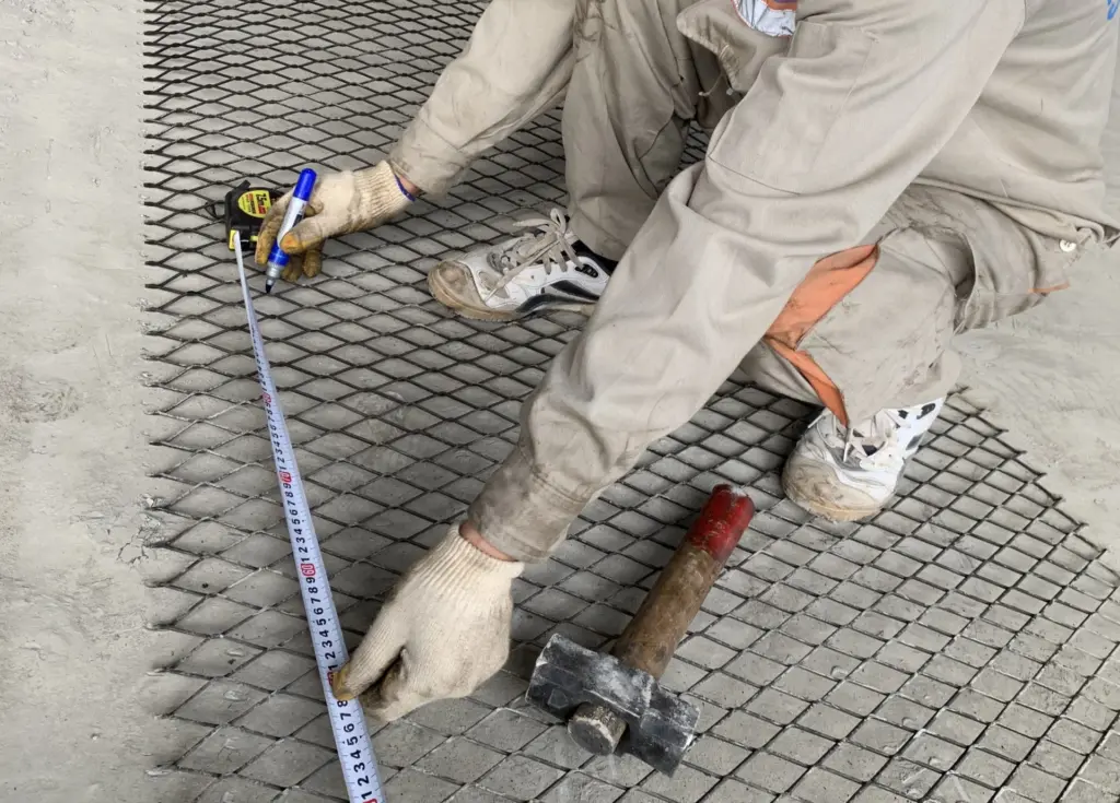
One issue that needs to be controlled from the preparation stage is mesh positioned directly against the wall.
If the required gap is lost, the material may not fully penetrate behind the mesh. The base of the lining may then fail to form correctly and become a location where separation from the substrate begins.
Values such as mesh spacing, water quantity, mixing time and installation conditions must be checked against the exact material grade being used.
4.2. Moisture sealing after finishing
After the surface is finished, the lining needs to be moisture-sealed within the specified period.
If the surface begins to dry before this step is performed, water retention during curing may be affected.
This is a mandatory waiting point governed by the material reaction. Adding more manpower does not make this process occur faster.
4.3. Three requirements that need to be determined before mixing
Divide the installation area
Large surfaces should be divided into installation sections rather than completed continuously as one large area.
The material shrinks during curing. Dividing the area helps control where stress accumulates.
Provide expansion joints
According to the documentation being used, where the operating temperature exceeds 50 °C, an expansion joint should be provided with a 5 mm rigid foam strip.
The reason is the difference in thermal expansion between the steel structure and the lining. The two materials do not change dimensions at the same rate as temperature changes.
The reinforcing steel mesh must be cut along the joint line. If the mesh remains continuous across the joint, stress continues to transfer into the adjacent area and the joint cannot perform its intended function.
Provide edge-retaining strips
At the boundary between lined and unlined areas, as well as at termination edges, a suitable steel retaining strip should be provided.
If the lining tapers down toward the edge, that location can become the starting point for detachment.
5. Initial heat-up curve after installation
For heated equipment, once the material has completed the required cold-curing period, the first heat-up should not go directly to operating temperature.
The 12-hour holding period needs to be included in the operating plan.
If the temperature rises too quickly while moisture remains inside the lining, steam may form suddenly and cause explosive spalling during the first start-up.
The schedule therefore needs to include:
- cold-curing time
- drying time
- holding time
- heat-up time to operating temperature
Actual installation duration includes more than only the time spent trowelling or spraying the material.
6. Rear-side weld studs
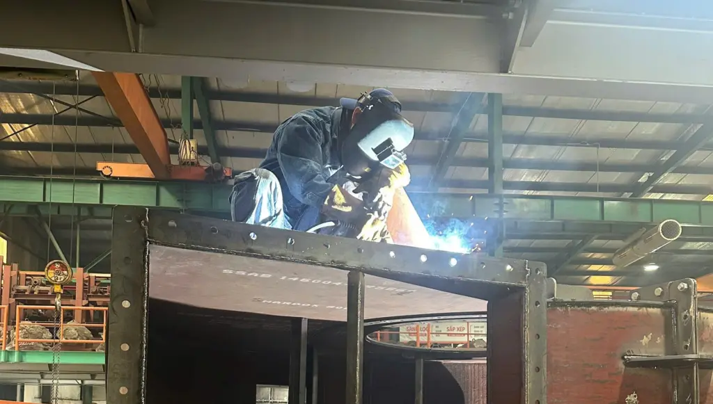
With this method, control points focus on connection dimensions, weld condition and the position of the bolt or stud head relative to the working surface.
The 3 mm clearance at the plug-weld location is an important control point.
If the weld metal extends too high and mixes into the hard-facing area, the interface can become a location that wears faster than the surrounding surface.
7. Adhesive bonding
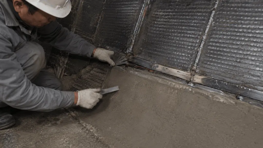
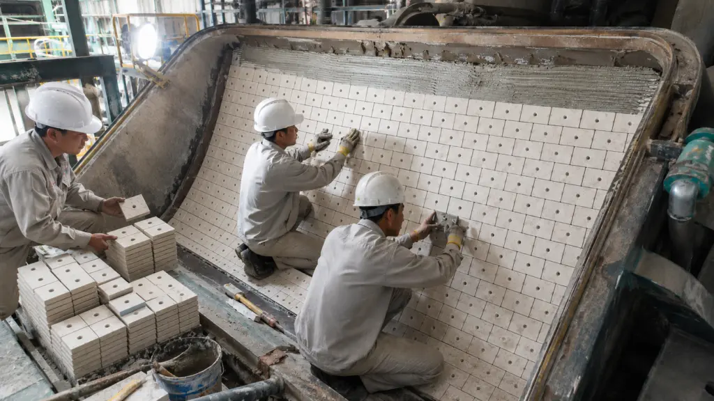
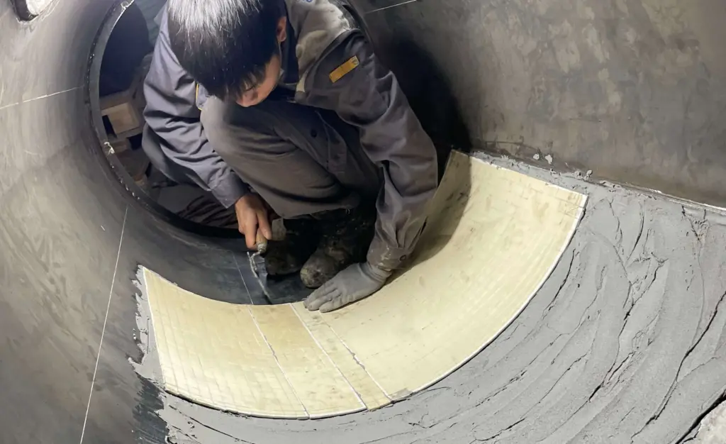
For adhesive bonding, mixing, adhesive thickness, usable time and, especially, full coverage at all four corners of the lining tile need to be controlled together.
7.1. Mixing, spreading and laying the tiles
Full adhesive coverage at the four corners is particularly important because these are the areas where the bonded joint is subjected to peel.
7.2. The 45-minute and 2-hour limits apply to different activities
The 45-minute limit is the pot life of the adhesive batch after mixing.
The 2-hour limit is the minimum waiting time before welding near the newly bonded area.
If the batch is mixed in too large a quantity, the adhesive may exceed its pot life before installation is complete.
If welding is carried out too early to shorten the schedule, heat from welding may affect the adhesive before it has had sufficient time to stabilize.
The batch size should therefore match the area that can be completed within the adhesive pot life, while nearby welding should be scheduled for the following stage.
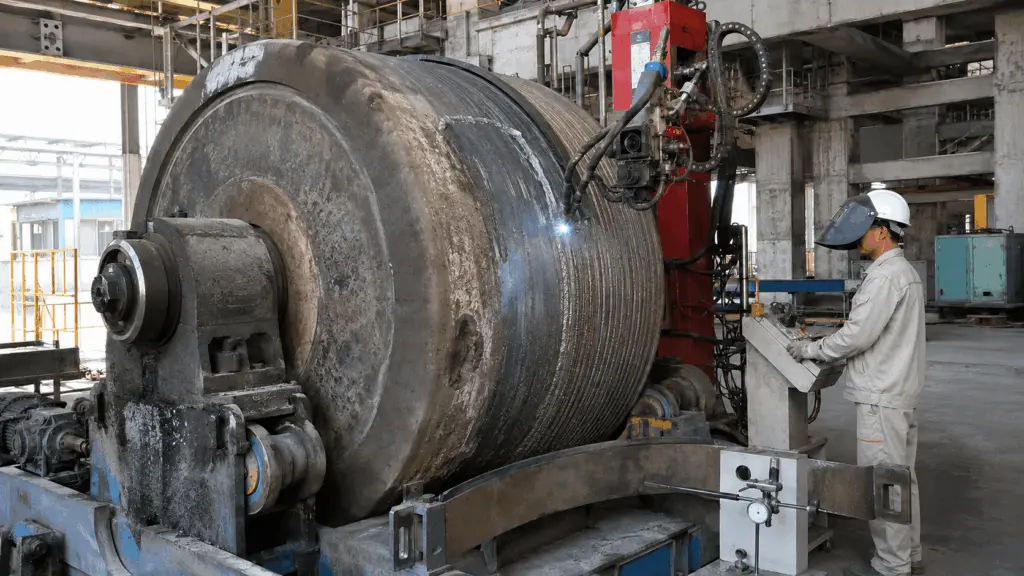
8. Welded steel rings
This method uses short tack welds with cooling intervals to limit heat input to the surrounding material.
If cracking appears around the welded location, the connection needs to be handled according to the applicable procedure.
The fact that the steel ring remains attached to the structure is not, by itself, enough to conclude that the location is acceptable.
9. Mandatory waiting times cannot be shortened simply by increasing manpower
The four fixing methods include steps that depend on material reaction or stabilization.
Important waiting periods include:
- adhesive pot life
- waiting time before nearby welding
- curing time
- moisture-sealing time
- drying and holding time
These periods cannot be shortened simply by increasing the number of workers.
If available downtime is shorter than expected, the work scope should be reconsidered rather than shortening mandatory material waiting periods without technical justification.
Waiting times therefore need to be identified during installation planning, not after work has already started.
10. Items that can be checked after installation without removing the lining
The four fixing methods allow several simple checks to be performed directly in the field.
These inspections do not require lining removal and can help identify certain attachment deviations before the equipment returns to operation.
However, the result only reflects the connection condition at the time of inspection. It is not a method for predicting the final service life of the lining.
11. Acceptable signs and corrective-action signs should be described in observable terms
An installation instruction is only truly usable in the field when the person performing the work can determine what constitutes an acceptable condition and what requires correction.
For example, an instruction such as “mix the adhesive thoroughly” is not sufficient for verifying the operation.
It should state:
- how long to mix
- the color of the mixture after mixing
- how the adhesive behaves when the tool is lifted
- signs indicating that the adhesive batch is no longer usable
This approach converts installation experience into observable criteria that installers, supervisors and engineering personnel can inspect and compare together.
The same principle applies to hollow sounds in monolithic linings, protruding stud heads and the condition of steel rings after welding.
12. Responsibilities during lining installation
Each stage should have a clearly defined responsible party so that the material solution and actual installation conditions are considered together.
A solution may be appropriate from a material perspective but still incomplete if the fixing method cannot be implemented under the actual accessibility conditions.
Installation feasibility therefore needs to be confirmed before the solution is finalized.
13. Scope of application and references
Most numerical thresholds in this article are taken from manufacturer installation guidelines for lining materials, including:
- mixing ratio
- adhesive pot life
- moisture-sealing time
- anchor-mesh spacing
- anchor dimensions and spacing
Three parameter groups have intentionally not been assigned fixed values:
- mesh spacing and spraying productivity for each grade
- tightening torque by bolt size
- tack-weld length and cooling time between welds
These parameters must be checked against the exact material and applicable instructions rather than filled in using estimates.
Three additional points should be noted when applying this article.
First, numerical thresholds vary by material. During installation, the documentation for the actual product being used must be consulted.
Second, post-installation inspections can identify certain attachment deviations at the time of inspection but do not determine the final service life of the lining.
Third, this article explains how to select a fixing mechanism and control installation. It does not determine which material group is the most suitable for a specific location.
The peel mechanism at tile corners is used to explain the loading state of bonded joints. Acceptable signs, corrective-action signs, work organization and post-installation inspection practices are based on Gia Anh’s field installation experience.