Part 4: Installing anti-adhesion linings
An anti-adhesion surface needs to be not only smooth, but also continuous along the direction of material flow. If raised edges, steps or abrupt joints appear, the bulk material may be obstructed, slow down and begin to accumulate at that exact location.
The performance of an anti-adhesion lining therefore depends simultaneously on the material, operating temperature and how the surface is arranged after installation.
The overlap direction, plate orientation, expansion gaps and bolt positions should be determined according to the actual direction of material flow, not only according to the geometry shown on the drawing.
1. Technical terms used in this article
2. A small raised edge can become the starting point for material build-up
A protruding edge on the surface can change the flow condition at that location.
The build-up process may develop in four stages:
From the final stage onward, the process can become self-reinforcing. Build-up slows the flow further, while the slower flow creates more favorable conditions for additional material adhesion.
A small raised edge is therefore not merely a surface-finishing issue. It can become the starting point for an entire build-up zone.
A smooth surface and a continuous surface profile are two different requirements. A surface may be very smooth but still contain a protruding joint. In that case, material may begin to accumulate at the joint and then spread into the surrounding area.
3. Operating temperature needs to be determined before the material is brought to the installation location
Anti-adhesion material groups have their own operating temperature limits.
If the actual temperature exceeds the material’s allowable range, installing the lining in the correct flow direction or properly treating the joints will not resolve the underlying issue.
Before the material is brought to the installation location, at least the following should be determined:
- operating temperature
- peak temperature
These values need to be checked against the temperature limit of the exact material being considered.
If the location exceeds the upper temperature limit, the issue lies in the operating range of the material, not in the installation procedure.
Temperature therefore needs to be checked before the material is finalized and installation is organized, rather than discovered only after the lining system has already been installed.
4. Install from downstream toward upstream
An important installation principle is to work from the downstream end back toward the upstream end.
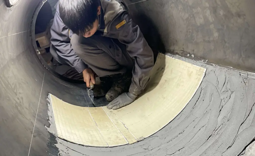
Each subsequent plate is arranged so that the overlap edge follows the direction of material movement.
If installation proceeds from upstream toward downstream, the overlap edge may face the incoming material flow. The bulk material then strikes a protruding edge directly, and this location may become the starting point for build-up.
A quick post-installation check can be performed using a simple action:
Run your hand in the actual direction of material flow. If your hand does not catch on an edge, the overlap direction follows the flow.
This check does not replace dimensional and installation requirements, but it can quickly identify an overlap edge installed in the wrong direction.
5. Three ways to treat joints without creating flow obstructions
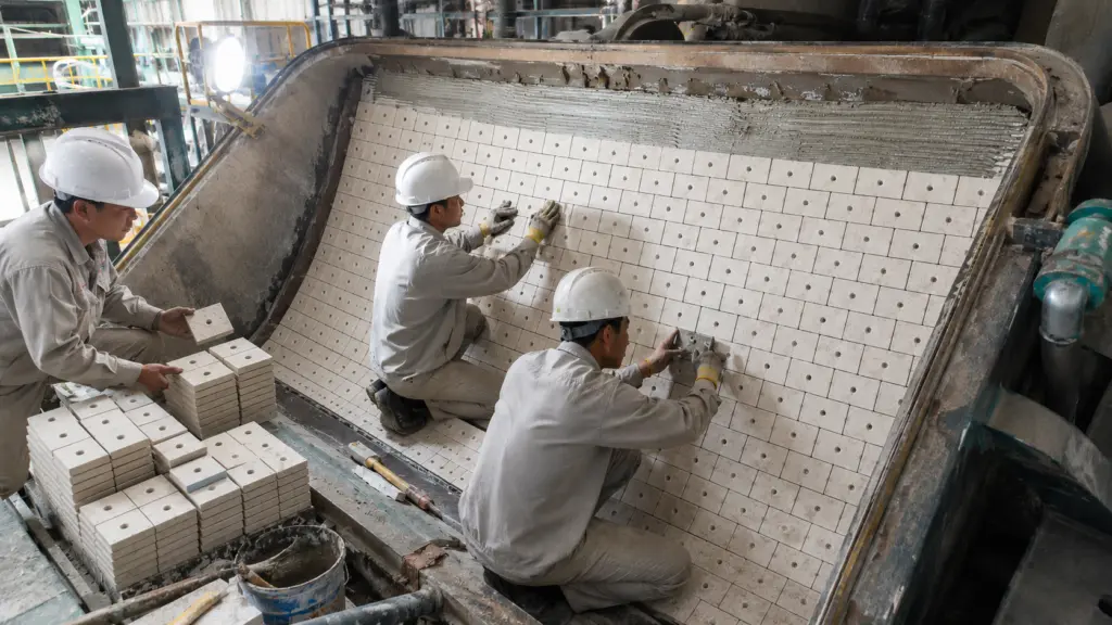
Not every location allows joints to be eliminated completely. Where plates need to be joined, the treatment should maintain surface continuity along the flow direction.
The condition to avoid is a rough cut edge facing upstream.
Even if the material itself has favorable sliding properties, a protruding cut edge or rough joint can still obstruct the flow and break the continuity of the working surface.
A joint should therefore not be evaluated only by whether the gap is closed. The orientation of the edge relative to the actual flow direction also needs to be considered.
6. Orient plate length along the flow direction to reduce cross-flow joints
Where plate orientation can be selected, the longer dimension of the plate should run along the direction of material flow rather than across it.
The objective is to reduce the number of joints crossing the material flow path.
Cross-flow joints are less favorable because the material flow acts on the joint across a larger width rather than sliding lengthwise over the edge.
Plate arrangement should aim to achieve three things:
- reduce the number of cross-flow joints
- keep the remaining joints aligned with the flow direction
- avoid raised edges or steps at the joints
Plate orientation is therefore not only about making efficient use of material dimensions. It is part of the design of the working surface.
7. Expansion gaps need to satisfy both thermal and material-flow requirements
The gap between plates needs to satisfy two requirements that tend to work in opposite directions:
- provide sufficient space for thermal expansion as temperature increases
- not be so wide that bulk material can become trapped in the gap
This issue requires particular attention with engineering plastics because their coefficient of thermal expansion differs from that of the steel substrate.
Gap dimensions should not be estimated visually.
The required value needs to be determined according to:
- material thermal-expansion coefficient
- plate dimensions
- actual temperature range at the location
The temperature range must be based on the operating conditions of the actual equipment rather than only on room temperature.
If the gap is too small, the plates may push against each other as temperature increases.
If the gap is too large, bulk material may enter the gap, creating a build-up point or exposing the plate edge to unfavorable loading.
8. Bolt heads need to be flush with or recessed below the working surface
For the engineering-plastic group referred to in the documentation, weld-stud fastening is commonly used instead of adhesive bonding because of the material’s surface characteristics.
After installation, the bolt head needs to be flush with or recessed below the working surface.
The condition can be checked directly:
- Acceptable: running a hand along the surface does not reveal a protruding bolt head
- Requires corrective action: the bolt head protrudes above the lining surface
A protruding bolt head creates two problems at the same time.
First, it becomes a flow obstruction and can become the starting point for material build-up.
Second, the bolt head is directly exposed to the material flow and may wear before the surrounding lining.
9. Three deviations that can make an anti-adhesion lining ineffective from the beginning
Some problems may arise during condition assessment or installation planning.
These situations are not necessarily defects in the material itself.
They result from incorrect condition assessment or installation planning.
Unlike some failures that only appear after long-term operation, these deviations may become apparent during the first operating cycles.
10. Items that can be checked immediately after installation
Several items can be checked using simple tools and procedures before the equipment returns to operation.
When checking surface continuity, lower the viewing angle until it is close to the level of the surface.
Small raised edges may be difficult to see from above but become easier to identify when viewed nearly parallel to the lining surface.
These checks should be performed immediately after installation and before the equipment returns to operation.
11. Three parameters belong to flow diagnosis, not installation parameters
Three parameters:
- material moisture
- adhesiveness
- sliding angle
are used to assess adhesion problems and the ability of bulk material to move.
They are not parameters used to instruct installation work.
Flow-diagnosis results are inputs for deciding the material and surface solution. Installation uses those results to arrange plates, joints and fixing points appropriately.
Therefore, if an anti-adhesion lining has been installed correctly but build-up still continues, the default response should not be to keep adjusting the installation method.
The material-flow conditions and flow design should then be reassessed.
12. Responsibilities during anti-adhesion lining installation
Decisions relating to flow direction, temperature and expansion gaps should be clearly assigned before installation begins.
Among these activities, the actual material-flow direction needs to be confirmed by the operations team.
Actual operating conditions may differ from old drawings or the original design diagram. The installation team should therefore not rely only on drawings when determining the overlap direction.
Similarly, expansion gaps need to be determined by the engineering team based on material data and temperature rather than estimated by installers at the site.
13. Scope of application and references
This article focuses on how to install anti-adhesion linings after the flow problem and material group have already been identified.
Three points should be noted when applying the content.
First, the article does not determine the root cause of adhesion at a specific location and does not replace the material-selection stage. Factors such as moisture, adhesiveness and sliding angle belong to the preceding material-flow assessment.
Second, the expansion gap needs to be calculated according to the exact material, plate dimensions and actual temperature range. There is no single gap dimension applicable to every location.
Third, if the surface has been installed in the correct flow direction, the joints do not create raised edges and the material remains within its allowable temperature range, but build-up continues, the operating conditions and flow design need to be reassessed.
Specific temperature limits and material parameters must be checked against the technical documentation for the actual product being used.
The mechanism by which an upstream-facing raised edge initiates material build-up is explained according to material-flow principles. The downstream-to-upstream installation principle and post-installation inspection practices are based on field installation experience used in Gia Anh’s methodology.