Part 1: Cutting and Forming
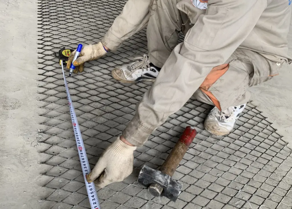
The way a material plate is cut at the beginning can directly affect the operations that follow.
Thermal cutting creates a heat-affected zone at the edge. Mechanical cutting leaves cold deformation, while waterjet cutting does not affect the material structure through the same mechanism as thermal cutting.
For this reason, the cutting method should be selected as part of the entire fabrication sequence, especially when the component will later be bent, drilled or further formed.
With high-hardness steel, an unacceptable cut edge, untreated burrs or an unsuitable bending radius may not cause immediate failure in the workshop. These areas can later become initiation points for microcracks or cracking during forming or after a period of operation.
1. Explanation of key technical terms used in this article
Before examining individual cutting and forming methods, several terms should be clearly understood because they appear throughout fabrication drawings, technical guidelines and workshop inspection activities.
Five terms related to cutting and bending
Two additional concepts also need to be noted:
In this article, preheating for thermal cutting refers to heating performed before thermal cutting. Preheating for welding is part of the welding process and is discussed in Part 2: Welding high-hardness steel.
2. The cutting method determines the edge condition and affects subsequent operations
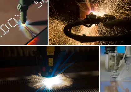
Different cutting methods leave different edge conditions. These conditions directly affect bending and forming in the next stage.
The cutting method should therefore not be selected independently of the work that follows.
If the component still needs to be bent, drilled or further formed, the material grade, thickness, cutting method and requirements of the next operation should be considered together.
The same material can have different edge conditions depending on how it is cut. A method that is convenient for cutting is not necessarily the most suitable for the next forming operation.
3. Thermal cutting: controlling temperature and cut-edge quality
Thermal cutting heats a narrow zone of the material to a high temperature while the surrounding steel remains at a lower temperature.
After cutting, the surrounding material draws heat away from the heated zone, causing it to cool rapidly. Where the technical documentation requires preheating, heating helps control the temperature difference and cooling rate.
Cracks may not appear immediately after cutting. Therefore, a freshly cut edge that looks intact is not sufficient to confirm that all fabrication conditions were appropriate.
3.1. Preheating according to the correct grade and thickness
Where the applicable documentation requires preheating, the temperature needs to be controlled before ignition and during the cutting process.
There is no single preheating temperature that applies to all high-hardness steels.
Before starting a fabrication batch, the correct material grade, thickness and applicable technical documentation need to be identified. A parameter used for a previous batch remains valid only if the current batch still falls within the same scope of application.
3.2. Preheating must remain within the permitted temperature range
Preheating is not simply about reaching a minimum temperature.
The temperature must remain within the range appropriate for the specific grade, thickness and fabrication method. A temperature below the requirement will not provide the intended cooling-rate control, while a temperature above the permitted range may affect the material condition.
Therefore, the required value should be taken from the current technical documentation rather than from a single memorized value applied to several steel grades.
3.3. Preheating requirements vary by cutting technology
Thermal-control requirements do not apply in the same way to every cutting method.
For laser cutting and nitrogen plasma cutting, preheating may reduce cut quality. These methods do not use preheating in the same manner as conventional thermal cutting.
Before applying any temperature requirement, the cutting technology and its corresponding technical guidance need to be clearly identified.
3.4. Inspecting the edge after cutting
The surface and edge quality of the steel should be inspected before the component moves to the next operation.
An unacceptable cut edge may not cause an immediate problem at the cutting stage.
Damage may only appear when the component is bent or after a period of operation. At that point, the original cause may be difficult to trace if the edge condition was not inspected and recorded earlier.
4. Mechanical cutting and punching must remain within the permitted range
Shearing and punching can only be used within certain hardness and thickness ranges. Outside the permitted range, cracking may occur at the edge.
The applicable range must be checked against the exact material grade. Where mechanical cutting is unsuitable, other methods such as thermal cutting or waterjet cutting should be considered according to the applicable technical documentation.
Before selecting a method, determine:
- material grade
- thickness
- cutting method
- forming requirements in the next operation
This information helps avoid a situation where a component has already been cut but the resulting edge condition is no longer suitable for subsequent bending or forming.
5. Ceramics, fused cast basalt, two-component plates and hard compounds require dedicated fabrication methods
Processes used for steel plate cannot be applied directly to every wear-resistant material.
A single piece of equipment may use steel, ceramics, fused cast basalt, hard compounds or two-component plates at the same time. Each material group has different characteristics and requires an appropriate fabrication method.
5.1. Plasma cutting two-component plates from the hard-facing side
For plasma cutting, the cut proceeds from the hard-facing side toward the steel backing.
The plasma jet naturally creates a bevel. Cutting in this direction places the bevel on the steel-backing side rather than on the working layer.
5.2. Air carbon arc gouging requires a suitable power source
Air carbon arc gouging uses direct current reverse polarity and requires a minimum open-circuit voltage of 60 V, with 80 V indicated as more suitable.
If the power source does not meet the requirement, the arc may extinguish during operation and leave pits on the surface.
5.3. Do not drill directly from the hard-facing side
The hard-facing layer referred to here has a hardness range of 700 to 820 HV. Conventional drill bits and milling cutters are not suitable for drilling directly through the hard-facing layer.
Three approaches can be used to produce holes:
All three approaches avoid direct mechanical drilling through the hard-facing layer.
6. Burrs must be removed before cold bending
Burrs may be small, but they are located at the edge where tensile stress is high during bending.
A sharp edge projection can become a stress concentration point. If the burr lies on the outer side of the bend, it may become an initiation point for cracking.
Before bending, inspect the edge directly:
- Acceptable: the edge has been ground smooth and no sharp projection can be felt by hand
- Requires correction: a sharp projection remains and must be ground before forming
This is a simple workshop inspection, but it directly affects the quality of the next operation.
7. Cold bending: determine all required data before forming
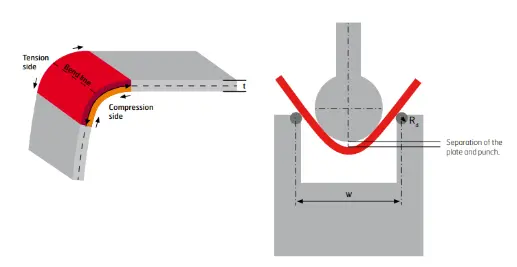
Before bending, at least three conditions need to be determined:
The bending direction should be shown on the drawing rather than decided only at the workshop.
Before starting a fabrication batch, the material grade, thickness range and rolling direction of the plate must be available.
If the rolling direction is unknown, there is insufficient data to determine the appropriate bending radius.
If small cracks appear parallel to the bend edge, the component should be reworked according to the applicable requirement rather than being rebent on the same component to correct the angle.
8. The sequence of cutting, bending and drilling depends on component geometry
There is no single sequence that applies to every component.
The case of holes located close to the bend line requires particular attention.
If the hole is drilled before bending, it may deform and become an initiation point for cracking. Bending first and drilling afterward helps avoid subjecting the hole to the forming process.
The fabrication sequence should therefore be determined from component geometry and the requirements of subsequent operations, not only from the convenience of individual fabrication equipment.
9. Operations to avoid when cutting and forming high-hardness steel
Several deviations identified in the overview article need to be controlled directly during cutting and forming.
The common point is that the consequences may not appear immediately after the operation is performed.
A newly completed component that looks normal is not sufficient evidence that all fabrication conditions were appropriate.
Handling and storage of leftover plate after fabrication are discussed in more detail in Part 6: Handling, storage and preservation.
10. Items that can be checked immediately in the workshop
The inspections in Part 1 focus on thermal condition, edge quality and forming conditions.
These inspections should be completed before the component moves to the next operation.
The objective is not only to identify unacceptable components, but also to prevent a deviation from the cutting stage from continuing into forming, welding or installation.
11. Responsibilities during fabrication
Each operation should have a clearly defined responsible department to prevent technical information from being lost when work moves from engineering to the workshop.
The cutting method should be determined from the beginning because it directly affects edge condition and forming capability in subsequent operations.
If the method is selected only for convenience or cost at the cutting stage, additional rework may be required or the component may no longer satisfy the original forming requirements.
12. Items to review before moving to the next operation
Before the component leaves the cutting and forming stage, confirm:
- correct material grade and thickness range
- cutting method suitable for the material and subsequent forming requirements
- preheating requirements identified according to the correct material and cutting technology
- actual temperature checked where required by the procedure
- cut-edge quality inspected and corrected
- burrs removed before bending
- plate rolling direction identified
- bending direction shown on the drawing
- bending radius complies with the applicable technical documentation
- cutting, bending and drilling sequence is suitable for component geometry
- cracks or abnormal indications have been addressed before moving to the next stage
This review helps prevent a deviation from cutting or forming from continuing into welding, installation or later fabrication operations.
Specific requirements for tolerances, geometry, bending direction and component dimensions must still be checked against the approved fabrication drawing.
13. Scope of application and references
This article identifies principles and control points for cutting and forming. Three points should be noted when applying the information.
First, preheating thresholds, bending radii and the applicable ranges for shearing and punching vary by material grade and thickness. Specific values must be checked against the correct technical documentation for the material being processed.
Second, there is no universal cutting, bending and drilling sequence for all components. The situations in this article provide guidance, but the final decision must be based on the actual geometry and requirements of the component.
Third, this article does not replace the approved fabrication drawing. Permissible tolerances, bending direction and specific requirements must still be shown and checked on the drawing.
EN 10163-2 is referenced for content relating to steel plate surface and edge quality.
Parameters relating to material grade, thickness, cutting method and bending radius must be checked against the manufacturer’s current technical documentation.
The principles concerning operation sequence, workshop inspection organization and handling of field indications are based on Gia Anh’s fabrication experience.