Part 5: Installation at the interface between two material groups
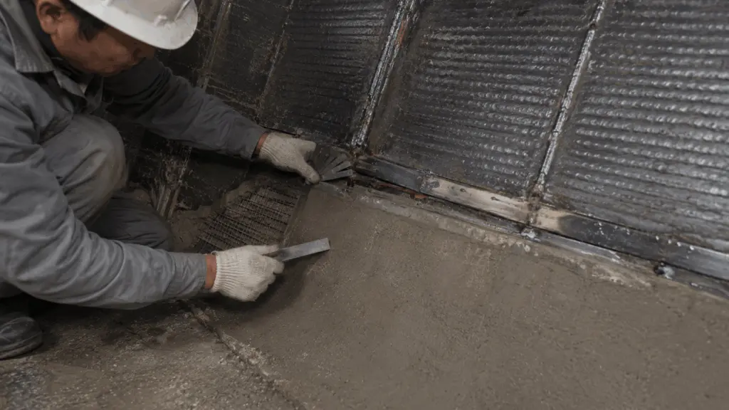
When two material groups meet on the same component, the interface becomes an area that needs to be controlled separately.
Each group may have its own technical documentation, operating limits and mandatory waiting times. However, the documentation for each material considered individually does not automatically address all the conditions that arise when the two groups are combined.
For this reason, installation at the interface involves more than simply placing two materials next to each other.
Before installation begins, the installation sequence, interface gap and applicable waiting periods need to be clearly defined. After installation, the interface itself should be measured, recorded and retained in the project documentation.
1. Explanation of key technical terms used in this article
The following terms are used throughout the planning, installation and inspection of interfaces between two material groups.
An interface is not merely a geometric boundary.
It is the location where the requirements of two material systems interact. Therefore, a parameter that is suitable for either material individually may not be sufficient to determine the condition applicable to the entire interface.
2. Three items that need to be defined before installation begins
Before two material groups are combined, three items need to be finalized.
If all three items have not yet been defined, installation should not begin even if the materials are already available at the site.
These decisions should also be documented rather than agreed only verbally.
If the interface develops damage after a period of operation, the records should make it possible to trace the original solution, the person who confirmed it and the date of the decision.
The interface is unique because no technical document for one material alone covers the entire combination.
A person with appropriate technical authority should therefore be clearly designated as responsible for the combination solution. The person’s name and confirmation date should be recorded in the documentation.
3. Prepare a combined threshold table before installation
When two material groups have different requirements, their conditions should be placed side by side before deciding how the interface will be installed.
The final step is particularly important.
If the documentation for one material does not specify a parameter, this does not mean that the value for the adjacent material can be applied to it.
Parameters that may need to be included in the table include:
- preheating temperature
- mandatory waiting time
- expansion gap
- upper temperature limit
- substrate preparation requirements
The combined threshold table does not replace the technical documentation for each individual material.
Its purpose is to place the two sets of requirements side by side so that compatible conditions, conflicting conditions and missing information can be identified before installation.
4. Installation sequence should be organized according to the waiting periods of each material group
Within the method described here, the group with the longer mandatory waiting period should be installed first.
This allows part of the waiting period for one material to run in parallel with work on the other group.
If the sequence is reversed, the schedule may need to absorb two waiting periods consecutively.
More importantly, the shorter waiting time of one group should not be applied to the group with the longer requirement.
Mandatory waiting periods relate to curing, stabilization or material reaction. Increasing manpower therefore does not mean that these periods can be shortened.
This sequence is an organizational principle within the scope of the method. In actual use, the specific conditions of the material combination still need to be checked.
5. Three interface configurations require different treatments
The geometry of the transition directly affects how the materials should be arranged and how the completed interface should be inspected.
Among these three cases, stepped interfaces require particular attention to the actual material-flow direction.
If the step is oriented incorrectly, it can become an upstream-facing raised edge. Material flow slows at the edge and creates conditions for build-up.
The principles relating to upstream-facing edges and continuous surface arrangement are discussed in Part 4: Installing anti-adhesion linings.
6. The interface should be measured directly after installation
Measurements should not be taken only at the center of each plate and then used to assume that the interface is also acceptable.
The interface itself is the area that needs direct inspection because this is where the requirements of the two material systems meet.
Measurements should be taken directly at the joint line.
Data taken from the center of each plate only describe the condition of each material individually. They do not indicate the quality of the transition area.
Interface records therefore have their own value.
A specific combination of two materials may not have manufacturer test data for that exact arrangement. Measurements taken at the plant then become the basis for comparison against the original technical decision.
These data can also support future installations. However, they remain reference data for the specific combination already installed and do not automatically validate a different material combination.
7. Material-combination decision records need enough information for traceability
A material-combination decision should retain the following information:
Among these, the reason for combining the materials and the responsible person are particularly important.
These two items distinguish a technically justified solution from a combination that was simply implemented in the field but can no longer be traced back to its original basis.
8. Three signs that the interface should be rechecked
Some deviations can be identified immediately after installation, while others can only be verified through installation records.
The third condition cannot be confirmed from visual inspection alone after work has been completed.
The records therefore need to retain the start and end times of mandatory waiting periods.
Without time records, the final condition of the interface cannot confirm whether the preceding installation requirements were actually followed.
9. Components using more than two material groups require each interface to be treated separately
When a component uses more than two material groups, the entire component should not be treated as one single interface.
Each material transition should be considered separately:
- prepare a combined threshold table for the two groups meeting at that location
- determine the installation sequence
- determine the gap and waiting periods
- measure the surface height difference after installation
- retain the corresponding interface records
In the example referenced in the source material, three operating zones using three material groups create multiple interfaces that need to be evaluated and measured separately.
The key issue is not the number of material groups, but the number of actual transition locations on the component.
10. Responsibilities during interface installation
Responsibilities for developing the solution, confirming installation feasibility and approving the combination decision should be clearly separated.
Two responsibilities should be distinguished.
The installation team confirms whether the solution can actually be implemented under the site accessibility conditions.
The person with technical authority is responsible for confirming the technical basis and conditions of the material-combination decision.
These two roles should not be merged.
11. Scope of application and references
This article focuses on how installation at the interface should be organized and controlled after the two material groups have already been selected.
Three points should be noted.
First, this article does not determine why the two groups need to be combined or which material groups are most suitable for the location. Material selection needs to be based on the operating conditions and failure mechanisms identified beforehand.
Second, the combined threshold table is a tool for placing requirements side by side and identifying conflicts. It does not replace the technical documentation for either material and does not replace direct measurement of the interface after installation.
Third, every new material combination still needs to be evaluated and measured. Data from one previous combination do not automatically validate another. This is also why the overview article identifies the interface between two material groups as a case where no single rule applies to every combination.
Parameters such as waiting periods, upper temperature limits, substrate preparation requirements and expansion gaps need to be checked against the technical documentation for the exact materials being used.
The method for preparing the combined threshold table, organizing the sequence according to mandatory waiting periods, treating steps according to material-flow direction and maintaining interface documentation is based on Gia Anh’s field installation experience.