Truck body structural weight reduction: From mass reduction to load-bearing design
A truck body that uses more steel, thicker plates and a heavier structure does not necessarily have greater load-carrying capacity. For specialized transport vehicles, the heavier the structure, the less mass remains available for payload.
Using high-strength steel can make it possible to reduce thickness at suitable locations while still meeting strength requirements. However, reducing thickness affects more than load-carrying strength. The structure must also control deflection, local stability, weld fatigue and actual fabrication capability.
Structural weight reduction should therefore be treated as a combined material and structural design problem rather than simply replacing thicker steel with thinner steel.
This knowledge series provides principles and evaluation methods for identifying where weight can be reduced, selecting high-strength steel, controlling the relevant technical limits and demonstrating that the structure remains suitable after the design is changed.
1. How tare weight affects payload capacity
Tare weight is the mass of the vehicle and truck body structure itself, excluding the transported load.
Based on the permissible gross vehicle weight, the basic relationship is:
Payload = Permissible gross vehicle weight – Tare weight
If tare weight is reduced by 1 kg while the permissible gross vehicle weight remains unchanged, the vehicle may gain 1 kg of payload capacity within the overall weight limit.
However, the actual benefit also depends on the type of cargo, body volume and axle load limits.
1.1. Three benefits of reducing tare weight
For vehicles that frequently carry heavy loads and operate close to the permitted weight limit, additional payload capacity can provide significant value.
For example, the weight saved on a truck body can be considered together with the number of trips per year and the remaining operating life to evaluate the economic benefit.
However, reducing tare weight does not always mean that more cargo can actually be carried.
If a vehicle carries low-density cargo and reaches its volume limit before reaching the weight limit, reducing tare weight may not increase the amount of cargo carried per trip.
Similarly, reducing total vehicle mass without considering load distribution across the axles may still not resolve axle load requirements.
1.2. Actual tare weight needs to be established before evaluating a solution
A vehicle that has had its body replaced, repaired or reinforced several times may have a different tare weight from its original configuration.
Before evaluating weight reduction potential, the vehicle documentation therefore needs to be compared with the actual condition.
In particular, it is not enough to identify only the total tare weight. It is also necessary to understand how that mass is distributed across the individual components.
When individual components cannot be weighed separately, their mass can be calculated from drawings, actual dimensions and thicknesses.
However, two types of data need to be distinguished:
WEIGHED: Mass determined by actual weighing.
CALCULATED: Mass determined from dimensions, geometry and material density.
Calculated results may not fully include welds, bolts, paint or auxiliary components.
When comparing the structure before and after a design change, the same method of determining mass and the same component scope should therefore be used.
The starting point for structural weight reduction is to establish the actual mass first, then identify where thickness reduction or structural changes may be possible.
This topic is covered in detail in Part 1: Reducing tare weight and increasing payload capacity.
2. Why can high-strength steel help reduce thickness?
When designing a load-bearing structure, thickness is not the only factor that determines how the material performs.
One important property is yield strength, which indicates the stress level at which permanent deformation begins.
High-strength steel has a higher yield strength and can therefore meet strength requirements at certain locations using a smaller cross-section.
However, three mechanical properties need to be distinguished when selecting the appropriate material.
2.1. Higher yield strength increases stress-carrying capability
When thickness is reduced, the load-bearing cross-section of the steel plate changes.
If the load and remaining geometry stay unchanged, stress in the plate may increase.
Using steel with a higher yield strength can help maintain the required stress-carrying capability without permanent deformation occurring.
This provides the material basis for many structural weight reduction solutions.
However, a higher yield strength does not automatically make the structure stiffer or reduce deflection.
Resistance to deformation also depends on geometry, thickness, span between supports and structural arrangement.
2.2. Higher-strength grades may reduce formability
When selecting high-strength steel, elongation and bending radius need to be considered in addition to yield strength.
For the perform® grades referenced in thyssenkrupp technical documentation, elongation generally decreases as the yield strength grade increases.
These values are compiled from perform® product documentation. The ranges may include different test conditions and different bases for determining elongation. They should not be used directly for comparison or acceptance inspection unless the test basis has been aligned.
This shows that the steel grade with the highest yield strength is not necessarily the most appropriate choice.
If the design requires deep-formed sections, formed ribs or tight-radius bends, material formability may become the limiting factor.
2.3. Steel selection needs to match the fabrication method
Two standard groups are used in this knowledge system:
Structural requirements and the fabrication method should be defined first, followed by selection of the yield strength grade and specific steel grade.
A steel grade that meets the load requirement but cannot be formed into the required section is still not an appropriate solution.
This topic is covered in detail in Part 2: Principles of reducing structural thickness with high-strength steel.
3. Three common technical limits when reducing thickness
High-strength steel can help meet strength requirements, but it does not address every change in structural performance caused by thickness reduction.
Three issues need to be controlled: deflection, local stability and weld fatigue.
3.1. Deflection increases as thickness decreases
A steel plate may still meet the strength requirement while deflecting more than the design allows.
Two conditions need to be distinguished:
Elastic deflection: The structure deforms under load and returns to its original shape after unloading.
Permanent deformation: The structure does not return to its original shape after unloading.
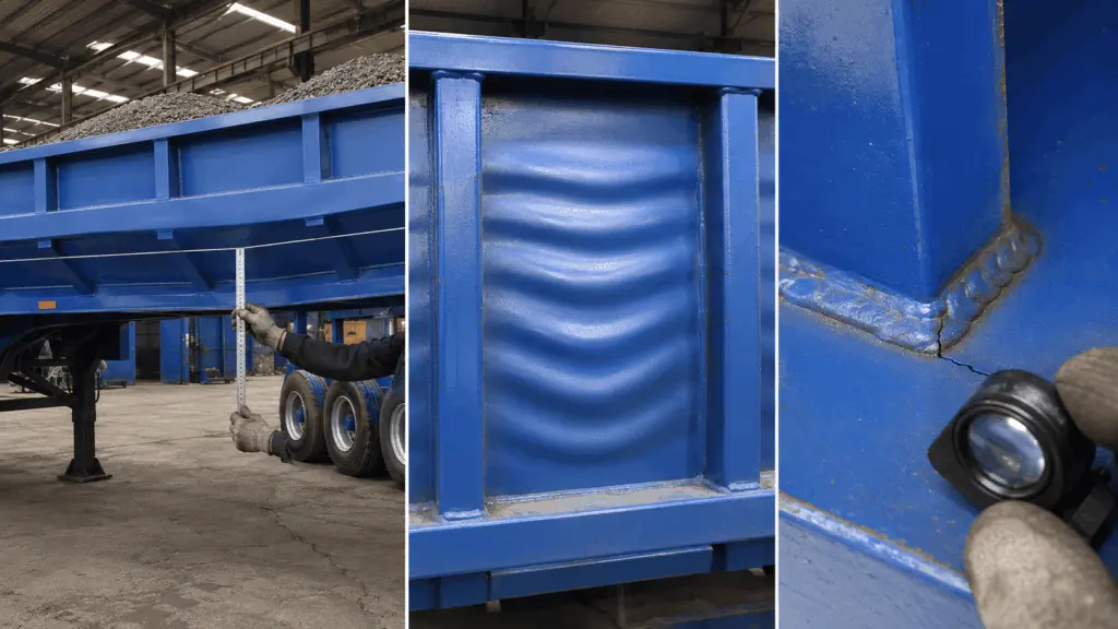
Inspection should therefore be performed both under load and after the cargo has been unloaded.
If measurement is carried out only while the vehicle is fully loaded, it may be difficult to determine whether the observed deformation is still within the elastic range.
3.2. Local stability depends strongly on geometry
A thin plate under compression may buckle before the material reaches its yield strength.
A common sign is a wavy surface, particularly in compressed regions between stiffeners.
Local buckling needs to be distinguished from impact denting.
Buckling is generally related to the stress state and plate geometry, while impact dents usually appear at locations directly struck by objects or cargo.
These two mechanisms require different evaluation and corrective approaches.
3.3. Weld fatigue is associated with repeated loading
Vehicle structures are regularly subjected to dynamic loading during operation.
Locations such as weld toes, the ends of intermittent welds or stiffener-to-plate connections can develop stress concentrations.
Under repeated loading, fatigue cracks may initiate and propagate.
In particular, when thickness reduction changes structural stiffness and natural frequency, the vibration response may also change.
If the natural frequency moves closer to the excitation range encountered during operation, vibration levels may increase and affect fatigue life.
Structural weight reduction therefore needs to be considered together with weld design and dynamic loading conditions.
Methods for identifying these conditions and taking measurements directly on the vehicle are covered in Part 3: Three technical limits when reducing thickness: Deflection, local buckling and fatigue.
4. How does a 20% thickness reduction affect the structure?
A simple calculation illustrates why it is not sufficient to increase the steel grade and then reduce thickness.
Consider a flat plate bending between two stiffeners. Assume that load, span and the other calculation conditions remain unchanged, then reduce the thickness by 20%.
The new thickness is 80% of the original thickness.
Calculation basis: a flat plate bending model in which load, span and corresponding geometrical and support conditions remain unchanged. These are mechanical relationships for the stated assumptions, not ratios that apply to every truck body structure.
The table shows that the three effects change at different rates.
First, stress increases by approximately 56%. Steel with a higher yield strength may be considered to meet the strength requirement.
Second, deflection nearly doubles. Increasing yield strength does not directly increase the elastic stiffness of the steel plate when the geometry remains unchanged.
Third, resistance to buckling decreases significantly. The plate may lose stability before the full stress capacity of the material is utilized.
Thickness reduction therefore needs to be accompanied by structural recalculation.
Higher yield strength expands the range of possible cross-sections. Structural geometry largely determines the ability to control deflection and stability.
5. Structural compensation options when reducing thickness
Once the governing technical limit has been identified, the design team can consider changes to geometry or material.
5.1. Changing the cross-sectional geometry
Instead of using a flat plate with multiple welded stiffeners, a U-shaped section or another suitable formed geometry can be considered to increase geometric stiffness.
This approach can improve resistance to deflection without necessarily increasing the number of welds.
Reducing welds in dynamically loaded regions may also reduce some stress concentration locations.
However, any improvement in fatigue performance still needs to be evaluated according to the structural detail and actual loading conditions.
5.2. Adding stiffeners
Stiffeners reduce the unsupported span of a plate and can therefore improve deflection and buckling resistance.
The trade-off is additional mass and more welded locations.
If stiffeners are positioned in dynamically loaded areas, weld design needs to be evaluated carefully to avoid unfavorable stress concentrations.
5.3. Increasing thickness or changing the steel grade
Increasing thickness can improve plate performance but reduces the tare-weight benefit.
Changing to a higher-strength steel grade can support the strength requirement, but it does not directly resolve all geometry-related limitations.
The appropriate solution therefore needs to be selected according to the governing technical issue, not only according to the desired weight reduction.
6. Bendability determines which sections can be fabricated
Changing the cross-sectional geometry is an important option in structural weight reduction. However, its feasibility also depends on the bending radius that the material and fabrication equipment can achieve.
As the yield strength grade increases, bending-radius requirements may change significantly.
6.1. Test bending radii for high-strength steel
Transverse 180° bend-test data according to ISO 7438 in perform® product documentation shows differences between steel grades.
These values are bend-test results under the conditions stated in the manufacturer’s documentation. They should not be used directly as recommended fabrication radii for every processing condition.
The table shows that increasing the steel grade may also introduce greater formability limitations.
A steel grade with high yield strength but requiring a large bending radius may not be suitable for a design with deep ribs or narrow sections.
6.2. Distinguishing bend-test results from fabrication recommendations
When material is introduced into the workshop, the correct fabrication guidance for the specific steel grade needs to be used.
For example, the source documentation provides the following recommendations:
These values are manufacturer fabrication recommendations under the corresponding conditions. The XAR® values are stated for bending perpendicular to the rolling direction. When bending parallel to the rolling direction, the source documentation requires the bending radius to be increased by approximately one plate thickness.
The two tables serve different purposes.
The first table presents bend-test results under specified test methods and conditions. The second provides guidance for actual fabrication.
The values from these two tables should therefore not be compared directly unless compatibility has been established for test conditions, bending direction, thickness and steel grade.
Another point to note is that for the perform® 650 and 700 grades referenced in the documentation, when thickness exceeds 8 mm, the minimum yield strength is reduced by 20 MPa, to 630 MPa and 680 MPa respectively.
Structural calculations need to use the guaranteed level applicable to the actual thickness range.
7. Zoning high-strength steel and wear-resistant steel on truck bodies
A specialized truck body may be exposed to two different groups of demands:
- wear and impact from cargo at contact surfaces
- structural and dynamic loading at beams, frames and other load-bearing components
These two groups need to be considered using different material requirements.
High hardness alone does not demonstrate that a material is suitable for use as a load-bearing beam or frame.
Similarly, high yield strength alone does not establish wear resistance at a cargo-contact surface.
Material selection therefore needs to be based on the actual function of each position.
7.1. Material zoning according to cargo type
The boundary between wear-exposed and load-bearing zones changes according to the characteristics of the cargo.
This provides an initial zoning approach and is not a mandatory material configuration for every truck body design.
The actual material zones need to be determined from cargo type, loading and unloading conditions, applied loads and structural design.
7.2. Transition zones need separate technical requirements
When wear-resistant steel and high-strength steel are used within the same structure, the connection between the two material groups needs to be considered separately.
The materials may have different requirements for preheating, interpass temperature, welding consumables and fabrication conditions.
Drawings therefore need to show the transition zones clearly, while the technical documentation needs to define a welding procedure appropriate for the materials being joined.
In particular, for two-component wear-resistant plate, it should not be assumed that the backing steel is guaranteed by the manufacturer for structural load-bearing applications.
The use of wear-resistant steel at cargo-contact surfaces and high-strength steel in load-bearing structures needs to be determined by function rather than by hardness or yield strength alone.
This topic is covered in detail in Part 4: Zoning High-Strength Steel and wear-resistant steel on truck bodies.
8. Welding and fabrication directly affect structural weight reduction
When changing to high-strength steel, the workshop should not assume that all welding and fabrication methods used for the previous steel grade can remain unchanged.
Particularly in dynamically loaded structures, welds and the heat-affected zone can become failure locations if the procedure is not appropriate.
The following need to be controlled:
EN 1011-2 is used as a reference for technical issues in steel welding, including crack-risk control and thermal conditions.
EN ISO 3834-2 relates to quality requirements for fusion welding of metallic materials.
An important principle is that welding consumables and joint design need to meet the load requirements of the entire structure rather than being selected only according to the base steel grade.
For dynamically loaded regions, the use of continuous welds, weld-toe geometry and the number of welds need to be considered according to the design requirements.
Adding more stiffeners can reduce deflection but also increases the number of welds. By contrast, changing the cross-sectional geometry may improve geometric stiffness without necessarily increasing the number of welds proportionally.
In particular, a welding procedure developed for wear-resistant steel should not be applied directly to high-strength steel unless its suitability for the materials, joint and load requirements has been established.
Further details are provided in Part 5: Welding and fabrication of high-strength steel for vehicle structures.
9. Weight reduction cases from practical documentation
There is no single tare-weight reduction percentage that can be applied to every truck body.
The achievable reduction depends on the original design, material thickness, selected steel group and the ability to change the cross-sectional geometry.
Four reference cases are provided:
These cases show that weight reduction can be achieved through changes in both material and design.
However, three points need to be distinguished.
First, each case starts from a different baseline. A design using more steel than required may offer greater weight reduction potential than a structure that has already been calculated and optimized.
Second, the reduction does not come only from changing the steel. In some cases, changing the cross-sectional geometry or removing reinforcing strips also contributes to the weight reduction.
Third, the published mass scope is not identical in every case. Some results refer to the equipment body, while others refer to a component or the truck body structure.
The reported reductions of 25-40% therefore represent four individual cases and are not guaranteed tare-weight reductions for other designs.
When evaluating a new truck body, the current mass needs to be established and the proposed changes recalculated for that specific structure.
10. Reducing thickness or retaining thickness to increase service life
Not every material change needs to target thickness reduction.
When using a material with more suitable properties, the operator may choose between two different approaches.
For example, on a truck body carrying sharp-edged and highly abrasive material, surface service life may be the priority.
By contrast, for a vehicle that regularly operates close to the permissible weight limit, tare-weight reduction may provide a more direct operational benefit.
Because these two design objectives are clearly different, tare-weight optimization needs to be considered separately for individual areas of the truck body rather than applied uniformly. Four areas should be reviewed during a tare-weight assessment:
These four areas are starting points for assessment and should not be assumed to be locations where thickness can automatically be reduced.
Actual reduction potential needs to be determined from loading conditions, applied loads and structural calculations.
11. Implementation process for truck body structural weight reduction
Based on the principles above, the implementation process can be organized into six steps.
11.1. Start from mass and operating conditions
If the current tare weight has not been established, there is no basis for calculating the actual reduction.
Similarly, if the vehicle regularly reaches its volume limit without reaching the permissible mass limit, the economic objective needs to be reconsidered before implementation.
11.2. Check structural limits before deciding how to reduce weight
The structure first needs to be assessed to determine whether it is governed by strength, deflection, stability or fatigue.
If the main issue is deflection, simply increasing the steel grade may not produce the required result.
If weld fatigue is the governing issue, adding stiffeners or increasing the number of welds needs to be considered carefully.
11.3. Demonstrate the result through documentation and measurements
A lighter structure needs evidence showing that the design still meets its load-carrying requirements.
The documentation should contain three main groups of information:
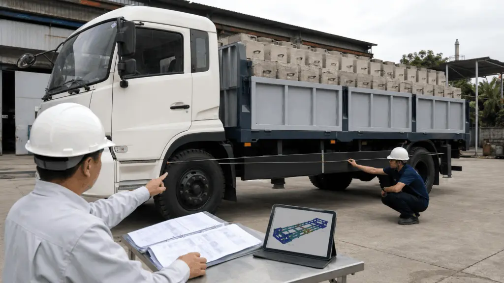
In addition to technical documentation, actual deflection on the vehicle can be measured using a tensioned line and ruler.
Measurements are taken under an appropriate vehicle load and again after unloading to record the deformation.
However, this visual measurement does not replace calculation of allowable deflection.
After the vehicle is delivered, monitoring may be organized at the initial stage, after six months and after one year according to the plan in the source documentation. These intervals support condition evaluation and are not mandatory inspection periods for every type of vehicle.
Further details are provided in Part 6: Demonstrating truck body load-carrying capacity through documentation and actual inspection.
12. Seven detailed articles on structural weight reduction
The Structural Weight Reduction knowledge series consists of seven detailed articles. The series progresses from evaluating economic value and selecting materials to structural design, fabrication and verification of the final result.
Part 1: Reducing tare weight and increasing payload capacity
Reducing the mass of a truck body can increase payload capacity within the permissible vehicle weight limit and may therefore provide economic value to the operator.
The article explains how to determine actual tare weight, break down mass by component and evaluate additional payload potential based on the number of transport trips.
It also explains how to identify areas that may be using more steel than necessary and how to distinguish actual weighed data from mass calculated from drawings.
Part 2: Principles of reducing structural thickness with high-strength steel
High-strength steel can make it possible to reduce thickness at suitable locations while still meeting structural strength requirements.
The article explains the roles of yield strength, tensile strength and elongation, and how to select a steel grade according to load requirements and the fabrication method.
It also covers the effects of bending radius, rolling direction and the declaration level of mechanical properties on the use of the material in an actual design.
Part 3: Three technical limits when reducing thickness: Deflection, local buckling and fatigue
Reducing thickness can increase deflection, reduce buckling resistance and change the dynamic loading behavior of the structure.
The article examines these three common technical issues, including how to distinguish elastic deflection from permanent deformation, local buckling from impact denting, and signs of fatigue cracking at welds.
It also presents methods for measuring and recording data on vehicles in operation.
Part 4: Zoning high-strength steel and wear-resistant steel on truck bodies
Different areas of the same truck body can be exposed to very different operating effects.
Floors and side walls in direct contact with cargo need to be evaluated for wear resistance, while beams, frames and dynamically loaded structural components need to meet structural load requirements.
The article distinguishes the functions of wear-resistant steel and high-strength steel, explains how to define material zones according to cargo type, and identifies the requirements that need to be controlled at transitions between the two material groups.
Part 5: Welding and fabrication of high-strength steel for vehicle structures
When high-strength steel is used, welding, bending and fabrication requirements need to be considered according to the steel grade and structural design.
The article covers factors such as preheating, interpass temperature, welding consumables, bending direction and weld arrangement in dynamically loaded regions.
It also explains the relationship between adding stiffeners, changing cross-sectional geometry and fatigue risk at welded connections.
Part 6: Demonstrating truck body load-carrying capacity through documentation and actual inspection
A lighter truck body needs sufficient evidence to confirm its load-carrying capacity after the design has been changed.
The article explains how to build a documentation package including a tare-weight comparison, structural calculations, material certificates and actual inspection results.
It also covers deflection measurement using a tensioned line and ruler, the distinction between elastic and permanent deformation, and post-delivery monitoring.
Part 7: Implementation roadmap for structural weight reduction in different situations
Not every manufacturer starts from the same problem.
Some workshops have an existing truck body model that needs to be lighter, some vehicles already show deflection or weld cracking, while other manufacturers are designing an entirely new truck body.
The article brings together the appropriate workflow for each situation, from establishing the initial mass and surveying the structure to material zoning, recalculation and verification of fabrication capability.
13. Responsibilities of the different functions
Structural weight reduction requires coordination between the operator, design team, procurement and fabrication workshop.
Responsibilities need to be agreed before implementation begins.
In particular, decisions to reduce thickness, change cross-sectional geometry or change material groups need to be based on structural calculations rather than only on workshop capability or the materials currently available.
14. Notes on applying this knowledge
First, the relationships between thickness, stress, deflection and buckling resistance presented in this article are based on defined mechanical models. These ratios should not be applied directly to every truck body design without verifying the calculation conditions.
Second, yield strength, elongation and bending radius need to be checked against the correct steel grade, thickness, rolling direction and version of the technical documentation. Guaranteed values, typical values and converted values need to be distinguished.
Third, the bending radius obtained from an ISO 7438 bend test is not the same as the recommended bending radius for fabrication. Design and fabrication need to use the applicable guidance for the actual material and verify formability in the workshop.
Fourth, high-strength steel and wear-resistant steel have different selection requirements. Whether a material can be used in a load-bearing position needs to be determined from its properties and intended product scope, not only from hardness or yield strength.
Fifth, the weight-reduction cases presented in this article are individual reference cases. The reduction achieved in one case should not be used to guarantee the result for another truck body design without survey and calculation.
Sixth, additional payload capacity also depends on permissible gross vehicle weight, axle load limits, body volume and operating conditions. Reducing tare weight may increase payload capacity, but it does not increase the legally permitted load limit of the vehicle. Any design and operating changes need to comply with the requirements applicable to the specific vehicle type.
Seventh, the suggested areas for potential steel reduction, survey sequence and cross-sectional changes reflect Gia Anh’s work organization experience and are not general requirements of a vehicle design standard.
Eighth, this article provides principles and evaluation methods and does not replace structural calculations. Any change in thickness, stiffeners, cross-section or load-bearing material needs to be checked against the standard applicable to the specific vehicle type and confirmed by an authorized person.
Effective structural weight reduction starts with accurately determining the mass and operating conditions of each component. High-strength steel can make thickness reduction possible, but structural geometry, fabrication capability and weld quality ultimately determine whether the solution can meet actual load-carrying requirements.