Part 1: Reducing tare weight and increasing payload capacity
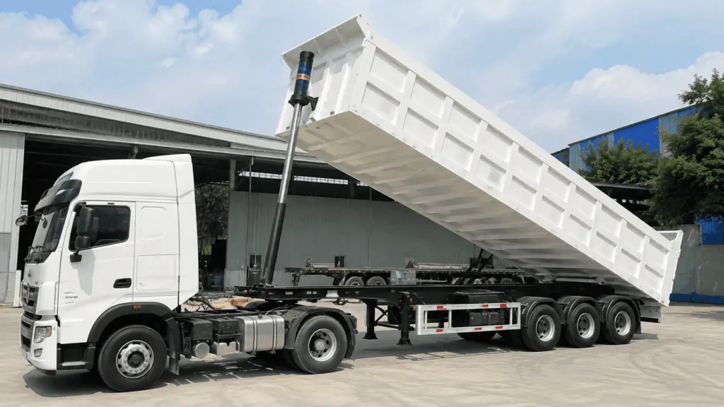
For specialized transport vehicles, the greater the mass allocated to the vehicle structure itself, the less mass remains available for cargo.
The basic relationship is:
Payload = Permissible vehicle weight limit – Tare weight
Reducing tare weight can therefore increase the amount of cargo carried per trip, provided that the permissible vehicle weight limit, axle load limits and cargo volume constraints are still satisfied.
In this article, “increasing payload” means increasing payload capacity within the permitted limits of the vehicle. It does not mean increasing the legally permitted load limit stated in the vehicle documentation.
The assessment needs to begin with one specific task: determining how much mass the vehicle currently allocates to each structural component. Only after this data is available is there a basis for identifying where weight reduction may be possible.
1. Tare weight directly affects payload capacity
Tare weight is the mass of the vehicle and truck body structure itself, excluding the cargo being transported.
If the permissible vehicle weight limit remains unchanged, any reduction in tare weight may become additional mass available for cargo.
For example, if a design change reduces the truck body structure by 500 kg, the vehicle gains 500 kg of potential payload capacity in terms of overall mass.
However, whether this entire margin can actually be used depends on:
- axle load limits
- body volume
- cargo type
- cargo distribution on the vehicle
- actual operating conditions
This is why the total weight reduction should not automatically be treated as an equal increase in cargo carried.
2. Reducing tare weight can create three levels of value
Reducing structural mass can provide three different benefits.
2.1. Additional payload
This is the most visible benefit when the vehicle regularly operates close to its permissible weight limit.
The value does not come from a single trip. The additional payload needs to be considered together with:
- number of trips per year
- remaining years of operation
- transport value per tonne of cargo per trip
When repeated across many trips and many years, excess structural mass can represent transport value that remains unused throughout the vehicle’s operating life.
2.2. Vehicle mass carried during operation
Even when the vehicle is not fully loaded, its own mass is carried throughout the journey.
When evaluating the effect on fuel consumption, both loaded and unloaded travel therefore need to be considered.
This article establishes only the principle. Converting the effect into fuel cost requires actual operating data from the vehicle fleet.
2.3. Axle load
Axle load limits are different from the overall permissible vehicle weight limit.
A tare-weight reduction solution may reduce load at certain locations, but the ability to redistribute mass still depends on vehicle design and cargo arrangement.
Axle load therefore needs to be evaluated separately. It should not be converted directly into a monetary value without sufficient supporting data.
3. The starting point needs to be data from the actual vehicle in operation
The assessment should not begin by selecting a steel grade or immediately defining a target thickness reduction.
The first step is to determine how much the actual vehicle currently weighs.
3.1. Compare against vehicle documentation
The following information should be taken directly from the vehicle records:
- permissible gross vehicle weight
- axle load limits
- registered or inspected tare weight
The documented weight provides a reference point.
If the vehicle has previously had its body replaced, reinforced, repaired or structurally modified, its current mass may differ significantly from the original configuration.
In that case, the actual mass of the vehicle in its current operating configuration is the appropriate starting point for structural weight reduction.
3.2. Do not rely only on total vehicle weight
Total weighing shows how much the entire vehicle weighs, but it does not show where the mass is located.
To identify opportunities for tare-weight reduction, the structure needs to be divided into component groups.
This changes the question from “How heavy is the truck body?” to “Where is the mass concentrated?”
That is the information required before moving into redesign.
4. When individual components cannot be weighed separately
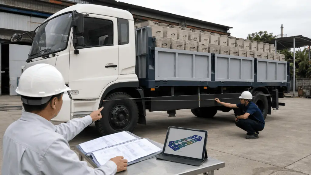
Many vehicles are already fully assembled, making it impractical to remove the floor, side walls or beams for separate weighing.
In this case, mass can be determined from actual measurements and drawings.
The data source needs to be clearly identified as CALCULATED, not WEIGHED.
These two data sources do not provide the same level of direct measurement.
WEIGHED means mass determined by actual weighing.
CALCULATED means mass determined from geometry, thickness and material density.
A CALCULATED value may be lower than the actual mass if it does not fully include:
- weld metal
- bolts
- small stiffeners
- paint
- accessories
- additional components introduced after fabrication
Before-and-after comparisons therefore need to use the same basis:
WEIGHED compared with WEIGHED.
CALCULATED compared with CALCULATED.
The actual weighed mass of an existing design should not be compared directly with a calculated drawing mass for a new design and the full difference treated as achieved weight reduction.
5. Areas to review before redesign
Based on field experience, four areas should be included in the initial review.
5.1. The upper side wall is an obvious area to review
The lower side wall is generally more directly exposed to cargo, particularly bulk material or sharp-edged material.
The upper side wall may operate under different conditions but still be fabricated to the same thickness because of production habits or to simplify fabrication.
This makes it an area that should be included in structural recalculation.
However, different operating conditions do not automatically mean that thickness can be reduced. Any change still needs to be determined from load requirements, deflection, stability and the overall structural design.
5.2. Beams need to be recalculated when the steel grade changes
When using High-Strength Steel, the original beam cross-section should not automatically be retained.
If only the material is changed while the entire original geometry remains unchanged, the benefit of the higher yield strength may not be converted into tare-weight reduction.
Conversely, reducing the cross-section without checking deflection, stability and fatigue can introduce new problems.
Changing the steel grade and changing the cross-section therefore need to be treated as a single structural design problem.
6. Operating data determines the value of the weight reduction
Once a potential reduction in tare weight has been identified, the result needs to be evaluated against actual operating conditions.
The required data includes:
The value per tonne-trip needs to come from the actual operator.
A material supplier or design organization should not assign an assumed value and then treat it as the customer’s economic data.
If the vehicle regularly reaches its volume limit before reaching the permissible weight limit, reducing tare weight may not increase the amount of cargo carried.
For example, with low-density cargo, body volume may become the limiting factor before total vehicle mass.
In this case, the value of tare-weight reduction needs to be assessed against other objectives rather than automatically converting the entire weight reduction into additional payload.
7. Do not define a reduction percentage before establishing the baseline
Reference cases may show that significant weight reduction has been achieved in practice.
However, they do not establish a universal reduction percentage for every design.
The achievable reduction depends on:
- initial tare weight
- current plate thickness
- current steel grade
- beam and stiffener arrangement
- ability to change the cross-sectional geometry
- loading conditions
- workshop fabrication capability
A truck body that currently uses thicker steel than necessary may still have substantial weight-reduction potential.
By contrast, a design that has already been carefully calculated and refined may have very limited remaining potential for further reduction.
The correct sequence is therefore:
Determine tare weight → Break down mass by component → Review load requirements → Calculate the weight-reduction solution.
A specific percentage target should not be set in advance, such as “the design must be exactly 10% lighter”, and then used to force design changes simply to meet that number.
8. Responsibilities of the different functions
Identifying the potential for tare-weight reduction requires data from several functions.
The vehicle modification history needs to be verified before historical data is used as the baseline.
A vehicle that has been reinforced several times may have an actual tare weight that differs significantly from its original configuration.
9. Notes on applying this knowledge
First, reducing tare weight can increase payload capacity within the permitted limits, but it does not increase the vehicle’s permissible total weight or axle load limits.
Second, WEIGHED and CALCULATED data need to be identified clearly and should not be mixed in the same before-and-after comparison.
Third, areas such as the upper side wall, lightly exposed floor zones, beams and plate spans between stiffeners should be reviewed. These are field-based starting points for assessment, not conclusions that thickness can automatically be reduced in those locations.
Fourth, if the vehicle reaches its volume limit before reaching its weight limit, reducing tare weight does not automatically increase cargo carried per trip.
Fifth, converting weight reduction into transport value needs to use the actual number of trips, remaining operating life and value per tonne-trip from the operator.
Sixth, this article helps establish the starting point for structural weight reduction. Any change in thickness, cross-section, stiffeners or load-bearing material still needs to be verified by structural calculations according to the requirements applicable to the specific vehicle type.
Structural weight reduction is only effective when the mass removed is converted into operational value.
Before considering a new material or design solution, it is therefore necessary to establish which limit the vehicle currently reaches, where the structural mass is concentrated, and whether the weight reduction will create additional payload, reduce the mass carried during operation, or improve load distribution.
Once these three points are clear, there is a sufficient basis to move into the design stage.