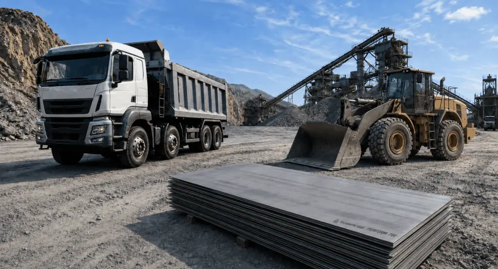
Part 3: Three technical limits when reducing thickness: Deflection, local buckling and fatigue
Reducing thickness does more than increase stress in the plate. As the structure becomes thinner, three other issues can become design limits: deflection, local buckling and weld fatigue.
The key point is that none of these three issues can be resolved simply by using a higher grade of High-Strength Steel. Higher yield strength may allow the structure to withstand greater stress before permanent deformation occurs, but deflection and stability depend strongly on geometry, while fatigue is directly related to repeated loading, vibration and connection details.
Before reducing thickness, it is therefore necessary to determine which limit is governing the actual structure and which compensation method is appropriate.
1. Three limits to check when reducing thickness
Three issues need to be considered:
- Deflection
- Local stability
- Weld fatigue
Each has different signs and requires a different response.
Increasing the steel grade mainly affects the stress level the material can withstand before permanent deformation begins.
By contrast, deflection and stability depend strongly on:
- thickness
- span between supports
- spacing between stiffeners
- cross-sectional geometry
Fatigue also depends on:
- number of load cycles
- vibration level
- weld details
- stress concentration locations
These three limits should therefore not be treated as problems that can be solved simply by increasing yield strength.
2. The three limits can interact
Deflection, stability and fatigue are not completely independent.
When thickness is reduced, structural stiffness changes. According to the source material, the natural frequency of the structure may also decrease.
If the natural frequency moves closer to an excitation range commonly encountered during vehicle operation, vibration levels may increase. Greater vibration can then introduce additional repeated loading at connections and welds.
A solution initially treated only as a thickness-reduction and deflection-control problem may therefore develop weld fatigue issues after a period of operation.
This is why all three limits need to be evaluated as part of the same structural system rather than treating each visible symptom separately.
3. First limit: Deflection
Deflection needs to be evaluated in two conditions:
- under load
- after the load has been removed
Measuring only when the vehicle is fully loaded is not sufficient to determine whether the structure is undergoing elastic deflection or has already developed permanent deformation.
3.1. Measuring deflection on an actual vehicle
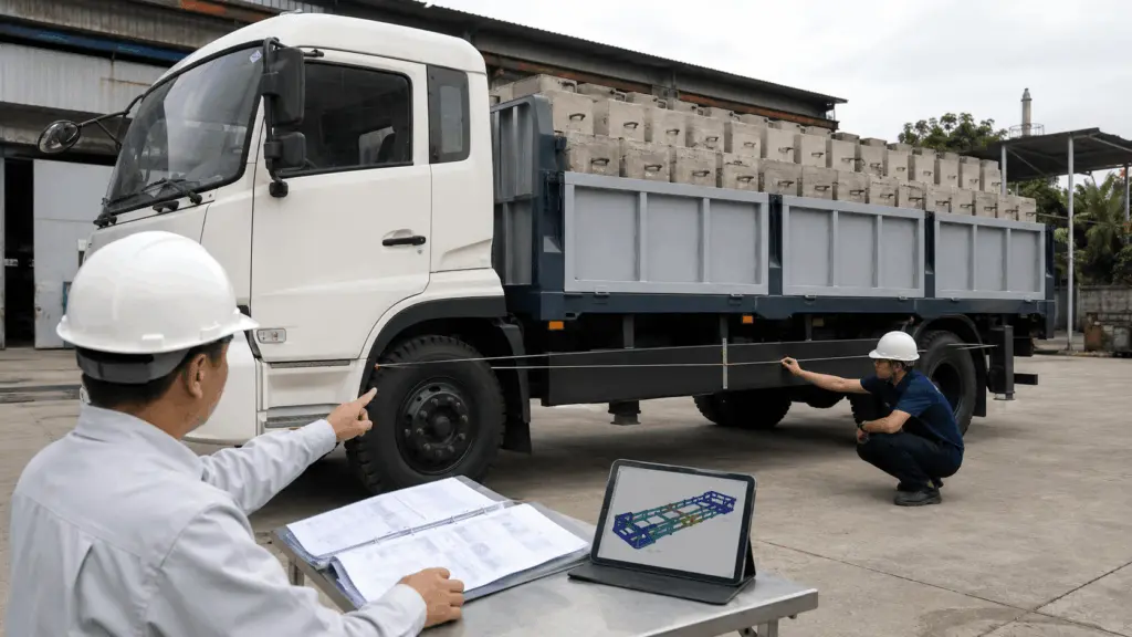
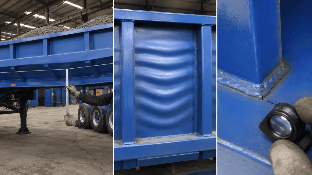
Under the measurement approach described in the documentation, a tensioned line and ruler can be used.
The important point is to use the same position and the same measurement method in both conditions.
If the measurement point or the way the line is tensioned changes, the two results will be difficult to compare.
3.2. Distinguishing elastic deflection from permanent deformation
This distinction is important.
A truck floor that deflects under full load is not, by itself, evidence that the structure has failed. If the floor returns to its original condition after unloading, the observed deformation is elastic.
By contrast, if the floor remains deflected or dented after the vehicle is unloaded, the structure has developed permanent deformation.
In this case, the design needs to be reviewed rather than simply adding reinforcement based on experience.
4. Second limit: Local stability
Local stability is a different problem from material strength.
A plate under compression may lose stability and buckle before the material stress reaches the yield strength.
The structure may therefore still have remaining strength capacity while no longer maintaining its intended working geometry.
4.1. Distinguishing local buckling from impact denting
These two forms of damage can be easily confused if only the surface appearance is considered.
Local buckling needs to be assessed in relation to:
- plate thickness
- stiffener spacing
- boundary conditions
- compressed region
Impact denting is more directly associated with localized loading on the surface.
Because the mechanisms are different, the two conditions should not be addressed using the same solution.
4.2. Why does increasing the steel grade not automatically solve buckling?
In a local stability problem, the plate may lose stability before the material reaches yield strength.
Increasing yield strength therefore does not automatically increase buckling resistance by the same proportion.
When thickness is reduced, the plate’s resistance to instability can also decrease significantly.
The solution generally needs to modify the geometry, for example by:
- reducing the unsupported plate span
- changing stiffener spacing
- changing the cross-sectional geometry
- adjusting thickness where necessary
This is why local stability needs to be calculated separately and should not be inferred from the steel grade alone.
5. Third limit: Weld fatigue
Vehicle structures are subjected to repeated loading throughout operation.
Each loading event, movement, vibration cycle and unloading event creates load cycles in the structure.
At stress concentration locations, particularly at welds, cracks may initiate and grow over time.
5.1. Distinguishing fatigue cracking from overload cracking
This table is intended for initial observation only and does not replace a full failure-cause assessment.
When a crack is identified, its location, length and the condition of the surrounding area need to be recorded before drawing conclusions.
5.2. Locations requiring particular attention
According to the source material, three locations require close inspection:
- weld toes in dynamically loaded areas
- ends of intermittent welds
- stiffener-to-plate connections where multiple joints are concentrated
These locations are also directly related to stiffener layout decisions.
Adding stiffeners can reduce plate span and improve deflection and local stability. However, new stiffeners also introduce additional welds.
If these welds are located in dynamically loaded areas, a solution intended to address deflection may simultaneously increase the number of locations requiring fatigue control.
Stiffener layout and weld design therefore need to be considered together.
6. Monitoring cracks over time
When fatigue is suspected, a single observation is not sufficient.
Crack length needs to be monitored across multiple inspections.
A sequence of measurements helps distinguish between a stable indication and a crack that continues to propagate.
Photographs should also be taken in a way that allows comparison between inspections rather than using only close-up images without a dimensional reference.
7. Identify the governing limit before selecting a compensation method
After measurement and observation, the field conclusion should link three elements:
Location → Sign → Measurement
For example:
Floor between two transverse beams → deflects under full load and returns after unloading → measured mid-span deflection is…
Or:
Side wall between two stiffeners → develops a wavy pattern under load → measured wavelength and stiffener spacing are…
This is more useful than a general statement such as “the body is weak” or “the plate is too thin”.
The survey result needs to help the design team determine whether the governing issue is strength, deflection, stability or fatigue.
Only then is there a basis for selecting the appropriate compensation method.
8. Quick identification table for vehicle inspection
This table supports the initial identification stage.
The final conclusion still needs to be based on measurements and structural analysis of the specific location.
9. Information that can be measured directly in the field
These measurements do not replace structural calculations, but they provide the design team with actual field data to identify the correct problem.
Natural frequency cannot be determined using these measurements.
Natural frequency cannot be established using only a tensioned line, ruler or the simple tools listed above.
Within the scope of this article, natural frequency is used only to explain the relationship between stiffness changes, vibration and fatigue risk.
The driver’s perception of vibration should not be used as a substitute for an actual measured frequency value.
However, information on the engine-speed range or operating conditions under which the vehicle vibrates strongly can still be recorded as input data for further technical assessment.
10. Selecting a response according to the governing limit
Once the main issue has been identified, the response needs to correspond to the governing mechanism.
A solution may need to address several limits at the same time.
For example, adding stiffeners may improve deflection and stability but also increase the number of welds. The design then needs to check the additional fatigue implications.
Conversely, changing the cross-sectional geometry may increase geometric stiffness without necessarily increasing the number of welded connections to the same extent.
There is no single compensation method that is appropriate for every position.
11. Responsibilities of the different functions
The survey schedule needs to match the actual operating condition.
If deflection under full load needs to be evaluated, the survey needs to be performed while the vehicle carries an appropriate load. Measurements on an empty vehicle cannot replace data under load.
12. Notes on applying this knowledge
First, this article provides methods for identifying and organizing measurements of signs observed on actual vehicles. It does not provide a complete structural design formula. Allowable limits need to be established through calculations and requirements applicable to the specific structure.
Second, deflection, local stability and fatigue can occur simultaneously. Identifying one governing issue does not mean that the other two are necessarily absent.
Third, permanent deformation is different from elastic deflection. If the structure does not return to its original condition after unloading, its load-carrying capability and design need to be reviewed rather than considering only the instantaneous deflection.
Fourth, a wavy surface may indicate a local stability issue, but the conclusion should not be based on appearance alone. The location, loading condition and structural geometry need to be considered.
Fifth, weld cracks need to be monitored over time and evaluated in the context of actual loading. This article does not provide criteria for determining the crack cause solely from its external appearance.
Sixth, the discussion of natural frequency is intended only to explain the relationship between stiffness, vibration and fatigue. Determining a specific natural frequency requires an appropriate measurement or calculation method.
Thickness reduction is technically justified only when the structure can still control all three associated limits. A steel plate may have sufficient yield strength, but if it deflects excessively, loses stability or increases the risk of weld cracking, the weight-reduction solution is still incomplete.
The survey therefore needs to identify the governing limit clearly so that the next design stage can focus on the geometry, connection details or dynamic loading conditions that actually need to be addressed.