Part 7: Implementation roadmap for structural weight reduction in different situations
After establishing the value of tare-weight reduction, the principles for using High-Strength Steel, the limits associated with deflection, stability and fatigue, material zoning and fabrication requirements, the next step is to identify the correct starting point for the actual situation.
Not every project follows the same sequence.
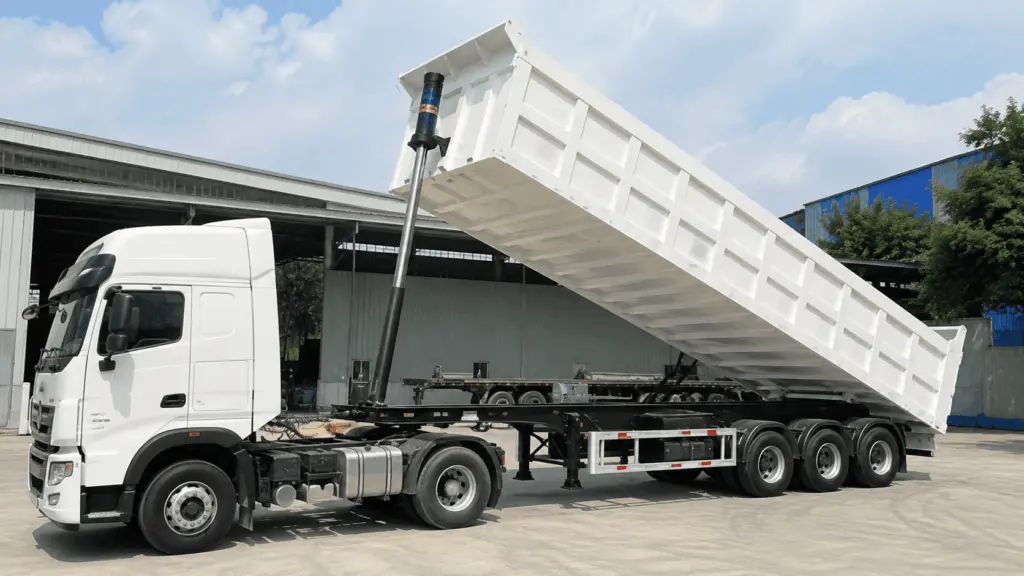
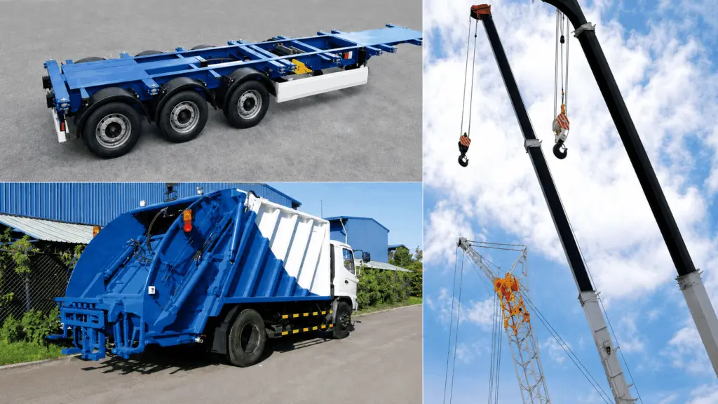
An existing truck body model that needs to be lighter should start with tare-weight data. A vehicle that already shows deflection or weld cracking should start with an assessment of its current condition. A new truck body design, meanwhile, should define from the drawing stage which areas are exposed to wear, which parts of the structure are load-bearing, and how the two material groups meet.
This article brings together three implementation roadmaps to help manufacturers determine what to measure first, what to calculate next, and when material selection should begin.
1. Situation 1: An existing truck body needs to be lighter
For a truck body model already in production, the process should not begin by immediately selecting a higher grade of High-Strength Steel.
The first step is to determine where the current mass is located.
1.1. Identify the vehicle’s actual limiting condition first
This step can change the entire direction of the project.
If the vehicle regularly reaches its weight limit before the body is full, reducing tare weight may create additional capacity for cargo.
Conversely, if the body regularly reaches its volume limit before the vehicle reaches its weight limit, tare-weight reduction does not automatically increase the amount of cargo carried per trip.
Other benefits may still exist in this situation, but the objective needs to be reassessed rather than assuming that additional payload is the primary basis for the project.
The principles for determining the value of the reduced mass are covered in Part 1: Reducing tare weight and increasing payload capacity.
1.2. Identify where the mass is concentrated
Once the operating objective has been defined, the next step is to determine where the structural mass is located.
Areas that should be reviewed include:
- floor and dump body floor
- lower side wall
- upper side wall
- longitudinal beams
- transverse beams
- frame
- stiffeners
- auxiliary components with significant mass
For example, the upper and lower side walls may currently use the same thickness even though they operate under different conditions.
This alone is not enough to conclude that the upper side wall can be made thinner, but it does indicate that the area should be included in the structural assessment.
Similarly, if a plate needs to remain thick because the stiffener spacing is too large, the appropriate solution may lie in the structural geometry rather than simply changing the material.
2. Situation 2: The vehicle already shows deflection, buckling or cracking
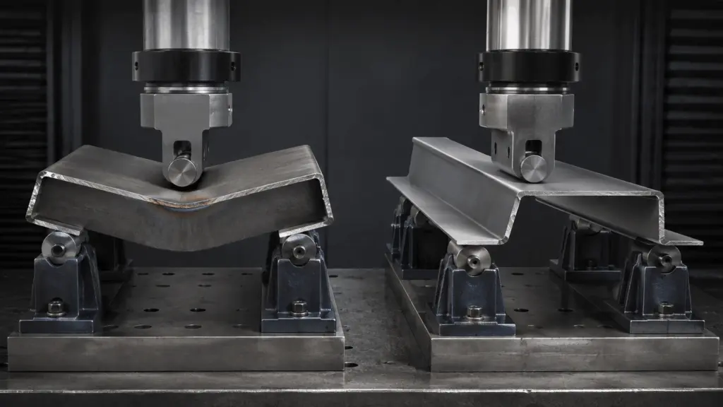
When a vehicle already shows abnormal signs, replacing the steel immediately may cause the original mechanism to be overlooked.
The governing mechanism needs to be identified before a solution is selected.
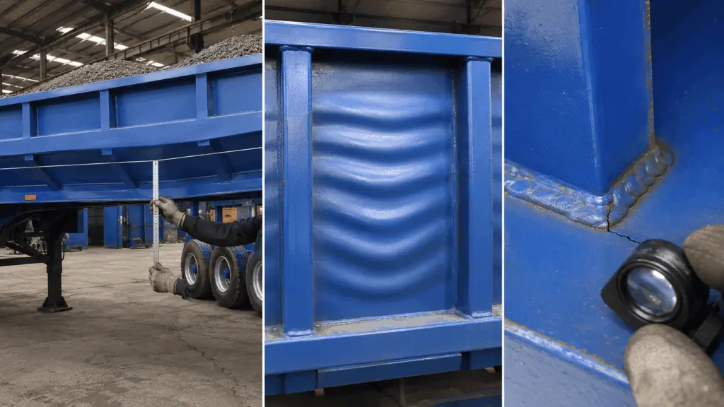
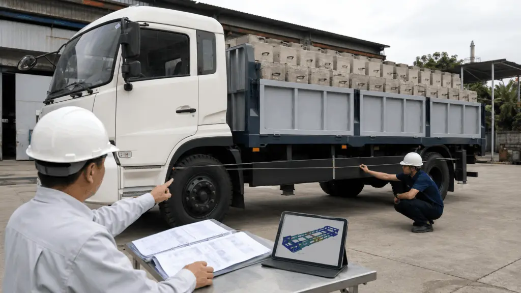
2.1. Measure deflection in two conditions
A simple measurement can be used as a starting point:
- Bring the vehicle to the required load condition.
- Tension a line between two defined points.
- Measure deflection at mid-span.
- Unload the vehicle.
- Measure again at the same position.
If the structure returns to its original condition after unloading, the observed deformation is elastic.
If it does not return, permanent deformation may have occurred.
These two conditions have different technical meanings and should not be addressed in the same way.
2.2. Do not use a single sign to determine the entire cause
A wavy plate should not automatically be classified as local buckling.
Similarly, a crack at a weld is not sufficient by itself to conclude that fatigue is the cause.
Additional information needs to be recorded, including:
- location
- load condition when the sign appears
- thickness
- stiffener spacing
- deformation pattern
- crack length
- deformation in the surrounding area
- development across repeated inspections
Detailed diagnostic methods are covered in Part 3: Three technical limits when reducing thickness: Deflection, local buckling and fatigue.
3. Situation 3: Designing a new truck body
With a new truck body design, the manufacturer has the advantage of not having to modify an existing configuration.
This is the appropriate stage to define material zones directly on the drawing.
The sequence should begin with the operating conditions of each area and only then move to steel grade and specific material grade.
3.1. Define material zones before selecting the specific grade
The floor, dump body floor or lower side walls may need to prioritize wear resistance.
Beams, frames and load-transfer components need to be evaluated according to the requirements of the load-bearing structure.
The boundary between these areas changes with cargo type.
For rock, slag or sharp-edged scrap, the wear zone may extend farther up the lower side wall.
For cargo that causes less wear, the wear zone may be smaller.
Material zoning is covered in Part 4: Zoning High-Strength Steel and wear-resistant steel on truck bodies.
3.2. Transition zones need to be included in the design from the beginning
When two material groups meet, the connection needs to be defined clearly on the drawing.
It should not be left for the workshop to decide after the materials have already been cut.
The following need to be defined:
- materials on both sides of the connection
- thickness
- joint configuration
- welding consumables
- thermal conditions
- welding procedure
- function responsible for approval
If the transition zone has not been resolved, the material solution is still incomplete even if each individual steel grade has been selected correctly.
4. Recommended reading sequence by rol4
The same knowledge series can be approached differently depending on the reader’s responsibilities.
4.1. For manufacturers
The first questions to answer are:
- where the potential weight reduction is located
- which limit is governing
- whether the workshop can fabricate the new solution
4.2. For structural design engineers
The focus is on the relationship between:
- yield strength grade
- thickness
- deflection
- stability
- fatigue
- material zoning
- welded details
4.3. For fleet owners
The most important information is whether the reduced mass creates actual operating value and what data demonstrates the performance of the new solution.
4.4. For procurement and quality functions
The main focus should be on:
- steel grade
- specific material grade
- declaration level of mechanical properties
- thickness
- documentation
- traceability
- welding and fabrication requirements
5. Three activities that can be completed before redesign begins
Some initial data can be collected directly from the vehicle before any new material is selected.
5.1. Measure deflection
Use the same measurement position under load and after unloading.
The result helps determine whether the structure recovers after loading or has developed permanent deformation.
5.2. Compare the upper and lower side walls
Record:
- thickness
- material
- mass
- stiffener spacing
- cargo-contact conditions
If both areas use the same configuration but operate under different conditions, this should be included in the structural assessment.
The result should not be used as an immediate basis for reducing thickness.
5.3. Record the conditions under which strong vibration occurs
The vehicle operator can provide information on:
- vehicle speed range
- engine-speed range
- road type
- loading condition
- location where vibration is most noticeable
This information does not replace vibration measurement, but it helps the technical team identify the conditions that require more detailed investigation.
6. When should a truck body review be carried out?
The objective of a truck body review is to establish the existing condition and identify missing data before changing the design. It should not begin with the introduction of a particular steel grade.
A review can include:
A review is particularly useful when:
- the vehicle has developed permanent deformation
- the side wall or floor shows signs of instability
- weld cracking occurs earlier than expected
- the truck body needs to combine wear-resistant steel and High-Strength Steel
- component mass cannot be determined because the vehicle is already complete
- the manufacturer wants to reduce tare weight but does not yet have baseline data
The outcome of the review should be design input data, not an immediate commitment to a specific percentage of tare-weight reduction.
7. Situations where structural weight reduction should not be the starting point
Not every vehicle problem is solved by making the structure lighter.
7.1. When volume is the limiting factor
If the truck body is already full while the vehicle remains below its weight limit, reducing tare weight may not create additional payload.
The manufacturer then needs to determine whether the customer actually requires:
- lower vehicle mass carried during operation
- a change in body dimensions
- improved service life
- resolution of another structural issue
The same economic argument should not be applied to every cargo type.
7.2. When axle load is the limiting issue
Reducing total tare weight does not automatically resolve the load on each axle.
If the actual limit is load distribution, the assessment needs to consider the location of the mass, truck body length, center-of-mass position and vehicle configuration.
This is a different problem from simply reducing the total kilograms of the structure.
8. General sequence from the existing condition to a new solution
Whether the project starts from an existing truck body or a new design, the process can be organized into four stages.
Stage 1: Define the problem
Clarify:
- whether the vehicle reaches its weight limit or volume limit first
- whether the objective is reduced tare weight or longer service life
- whether deflection, buckling or cracking is already present
- cargo type and operating conditions
Stage 2: Collect data
Record:
- tare weight
- mass of individual components
- thickness
- cross-section
- stiffener spacing
- deflection
- weld condition
- wear-exposed areas
Stage 3: Design the solution
Define:
- steel grade
- thickness
- cross-sectional geometry
- stiffener layout
- material zoning
- transition zones
- welded connections
Stage 4: Verify fabrication capability and demonstrate the result
Check:
- bending radius
- rolling direction
- welding procedure
- welding consumables
- traceability
- structural calculations
- tare weight after fabrication
- actual inspection results
This sequence helps prevent the steel grade from being selected first and the structure then being forced to adapt around it.
9. What should the final documentation package contain?
A complete solution should retain enough data for the functions involved in subsequent stages to verify the decisions made.
This documentation also provides a basis for evaluating subsequent truck body designs rather than starting from zero for every project.
10. Responsibilities of the different functions
Every decision needs to be converted into clear data or requirements in the documentation.
Information that directly affects load-carrying capacity should not exist only as verbal communication between the design team and the workshop.
11. Notes on applying this knowledge
First, not every structural weight reduction project begins with steel selection. The starting point depends on the existing vehicle, observed field conditions and operating objectives.
Second, a vehicle that reaches its volume limit before its weight limit may not gain additional payload from tare-weight reduction. The actual limiting condition needs to be identified before the benefit is calculated.
Third, if a vehicle already shows deflection, buckling or cracking, the governing mechanism needs to be diagnosed before changing the material or adding reinforcement.
Fourth, for a new truck body design, the areas using wear-resistant steel, High-Strength Steel and the transition zones should be defined from the design stage.
Fifth, vibration information provided by the operator is only initial field data. It should not be used as a substitute for vibration measurement or analysis when a specific frequency needs to be determined.
Sixth, a truck body review is intended to generate design input data, not to provide an immediate commitment to a specific tare-weight reduction percentage.
Seventh, any change to thickness, cross-section, stiffeners or load-bearing materials still needs to be verified through structural calculations and the requirements applicable to the specific vehicle type.
A sound structural weight reduction roadmap does not begin with the question “How many kilograms can we remove?” It begins by identifying what is currently limiting the vehicle.
Once the operating limit, structural condition and fabrication capability are clear, the manufacturer can determine which parts should remain unchanged, which parts need to be redesigned and which parts genuinely offer potential for weight reduction. This approach ensures that every change on the drawing has a clear technical basis before it reaches production.