Part 1: 4 factors to measure when conducting material wear surveys in industrial plants
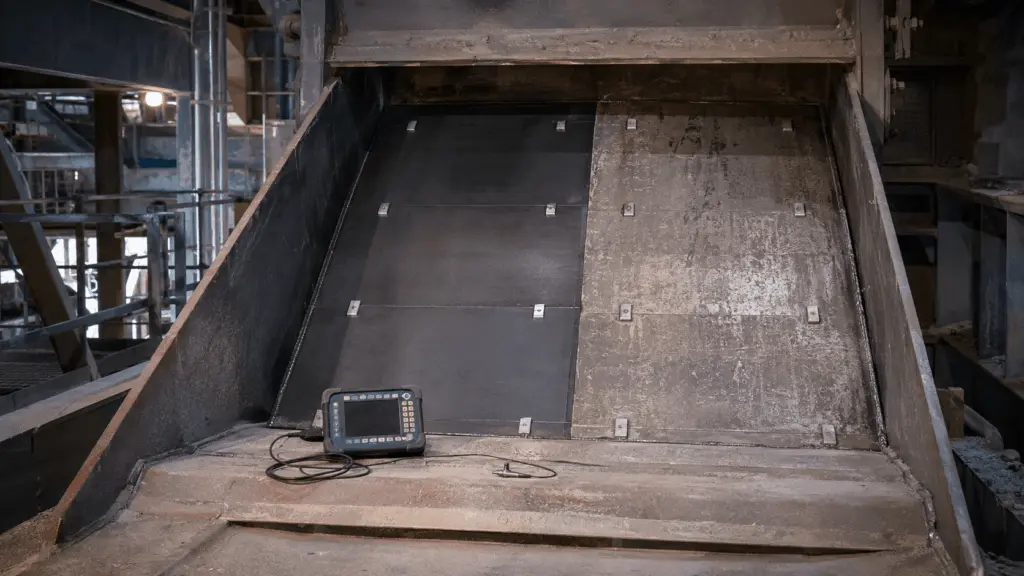
The four baseline groups of factors that need to be recorded at a location are wear, temperature, impact, and corrosion. However, correctly identifying the factors to be measured is only the first step. The value of the data also depends on the sampling location, the measurement time, and how the accompanying conditions are recorded.
A material sample taken from the wrong location or a temperature value measured only while the production line is operating under steady-state conditions can cause the survey results to deviate from the conditions at the location where damage is actually occurring.
Therefore, each measurement needs to answer three questions: what parameter is being measured, which location the value represents, and under which operating condition it was recorded.
1. Each factor needs to be converted into usable data
The name of the material is not a measurement.
Information such as “iron ore” identifies the type of material but does not indicate particle size, particle hardness, solids concentration, flow velocity, or the angle at which the material acts on the surface. These are the data used to describe the operating conditions at the surveyed location.
Instead of simply recording: “Iron ore, large material, severe wear,” the survey record needs to clarify the particle-size range, particle hardness, solids concentration, flow velocity, and the direction in which the material flow acts on the equipment.
Material flow is also often non-uniform. Multiple particle sizes and different particle types with different hardness levels may occur simultaneously. Therefore, particle size and hardness should be recorded as an actual range of values rather than reduced to a single figure.
The maximum lump size needs to be recorded separately from the particle-size range. Large lump size is related to impact loading, while the particle-size range is one of the data points used to evaluate wear conditions.
2. Measure the 4 groups of factors at the site
2.1. Wear: record 5 parameters of the material flow
For wear, the five parameters to be considered are particle size, particle hardness, solids concentration, flow velocity, and angle of incidence.
Particle size must be obtained from the material flow causing the wear
The data need to reflect the actual material flow in contact with the surface being surveyed, not a conveniently accessible sample taken elsewhere.
If sieves are not available at the site, a reference scale can be placed next to the sample and photographed in the same frame to estimate the size range.
A value obtained from an image remains an estimated value. The survey record needs to reflect this correctly and must not present an estimated value as a direct measurement.
Particle hardness assessment needs to identify the hardest constituent
Particle hardness can be checked in the field using a Mohs hardness test pencil set.
The method is to perform scratch tests on multiple particle samples using different hardness levels in the test set in order to determine the hardness range present in the material flow.
The key point is that the hardest particle type may not be the most abundant one.
For example, a material flow may contain both iron ore and silica sand:
If the entire material flow is recorded as “approximately 6,” the hardness level of the harder constituent is reduced in the recorded data.
During testing, multiple samples should be checked at different times during the shift, the hardness range encountered should be recorded, and the maximum value should be identified. Where possible, it should also be recorded whether the hardest constituent is a major constituent or occurs only in a small proportion.
The measured Mohs value should not be converted independently into Vickers or Brinell hardness for direct comparison with steel. Mohs-to-Vickers conversion tables apply only to the corresponding reference minerals. For engineering materials, data for the specific material grade need to be used.
Solids concentration depends on the sample being completely dried
Solids concentration is the mass fraction of solids in the material flow. It is determined by taking a sample, weighing it in the wet condition, drying it completely, and then weighing it again.
The critical control point is the drying step. If water remains in the sample when it is reweighed, the solids concentration result will be incorrect.
Flow velocity needs to be recorded together with locations where the flow changes direction
At many locations in a plant, flow velocity is difficult to measure directly. It can be determined indirectly using the two methods stated in the source:
- calculate it from flow rate and cross-sectional area
- measure the time taken for a marker to travel through a section of known length
These two methods provide average values. Local velocity in a zone where the material flow changes direction may differ significantly.
Therefore, together with the velocity value, the survey record needs to clearly identify the location where the flow changes direction. This information is important when evaluating zones subjected to stronger effects than the rest of the material-handling path.
The technical source used for this article refers to maximum flow-velocity ranges of 20–35 m/s for different lining material groups. These data are intended for the material-selection stage and are not thresholds for drawing an immediate conclusion during the survey stage.
The angle of incidence must be measured at the actual surface subjected to impact
The angle of incidence is the angle between the flow direction and the surface plane.
It can be measured with a protractor at the surveyed location. Surface marks also provide information for further evaluation: a small angle is often associated with long, shallow marks, while a large angle, close to perpendicular, is often associated with rounded indentation-type marks.
The identification of wear mechanisms based on surface-mark morphology is presented separately in the article 4 types of wear and how to identify them from the marks they leave.
2.2. Temperature: record both operating temperature and peak temperature
A temperature measurement taken while the production line is operating under steady-state conditions does not describe the full range of thermal conditions to which the material is exposed.
The two values that need to be distinguished are operating temperature and peak temperature.
Operating temperature reflects the normal working condition. Peak temperature may occur under a different operating condition of the production line and can easily be overlooked if measurement is taken only at one point in time.
Two instruments are used for two different purposes:
- an infrared thermometer for scanning and identifying temperature zones that require attention
- a contact thermometer for obtaining a measurement at the specific location
Temperature measurement methods and common measurement errors are discussed in greater detail in the article Temperature – the factor that changes the rules for material performance. At this survey stage, the two requirements that need to be maintained are recording both temperature conditions and using the appropriate instrument for the measurement purpose.
2.3. Impact: determine drop height, maximum lump size, and frequency
The three primary data points are drop height, maximum lump size, and impact frequency.
Among the three parameters, the maximum lump size needs to be observed over a sufficiently long period. Large lumps may occur infrequently and may not necessarily appear while the survey team is present at the location.
Therefore, this data needs to combine field observation with information from the personnel directly operating the equipment.
2.4. Corrosion: record moisture, pH, and chemical composition
The main information to be considered includes moisture, pH, and chemical composition.
For pH, the sampling location has a direct effect on the meaning of the measured value. Standing water at the location may already have been in contact with the material and may have conditions different from those of the original supply water.
Chemical composition should also not be inferred solely from the name of the material. The information needs to be checked against the plant’s material records.
3. Measurement order prioritizes data that change over time
Access to equipment in a plant is often available only within a limited time window.
The work sequence should prioritize data that may change or cannot be reproduced in the same condition after the equipment has stopped. Information that is less time-dependent can be collected later.
The general principle is to prioritize data that change over time, followed by measurements that are less dependent on the operating condition.
Within the sequence above, marking measurement points and taking photographs are particularly important. This takes little time but determines whether the next inspection can return to the exact same locations.
4. Equipment set for field surveys
The survey tool set within this scope includes:
- thickness gauge, tape measure, protractor
- infrared thermometer, contact thermometer
- moisture meter, pH paper
- Mohs hardness test pencil set
- reference scale to be placed within the photograph frame
- voice recorder
Before conducting the survey, use a reference standard to recalibrate the measuring equipment.
Note on portable hardness testers
Portable hardness testers have measurement error compared with laboratory testing. The level of error needs to be known before the result is used to support a technical conclusion.
Results from portable equipment may be used for preliminary field assessment. The use of measurement results for acceptance purposes needs to be determined separately according to the applicable requirements.
Hardness measurement errors and the effect of each type of error will be presented separately in the article group on Standards, Certification and Inspection.
5. The data source must be identified together with the measurement
Not all data collected during a survey are measured directly by the engineer while present at the site. Some information needs to be provided or confirmed by operating personnel and plant records.
Maximum lump size is one item that requires particular attention. It cannot always be determined within a few minutes of surveying because large lumps may occur infrequently.
Personnel who operate and monitor the equipment on a daily basis provide this historical information. Equipment design specifications should not be used as a substitute for the conditions actually occurring during operation.
6. Limitations when using survey data
The four groups of wear, temperature, impact, and corrosion provide the minimum baseline for beginning the assessment of a location. Depending on the operating conditions, some locations may also require additional parameters such as sulfur content, agitation speed, or thermal shock cycles to be considered.
Three limitations need to remain clear.
First, a value obtained from an image containing a reference scale remains an estimated value. This method supports documentation when sieves are not available at the site, but it does not convert an estimated value into a direct measurement.
Second, portable measuring equipment has measurement error. The results may be sufficient for preliminary field assessment but are not automatically sufficient for use as acceptance criteria.
Third, the sampling, weighing, and drying method is used to determine the solids fraction in the sample. The measurement sequence, the method for selecting the sampling location, and the field implementation considerations are methods used by GAC during actual field surveys and are not a general standard applicable to all survey activities.
In summary, a measurement is valuable only when the data correctly represent the location and operating condition being evaluated. Therefore, a survey does not end with obtaining a number; it must also preserve the location from which the value was obtained, the operating condition, and the method by which the data were generated.